Gas Valves & Regulation: Pressure Control and System Diagnostics for Global Industrial Operations
Understanding Pressure Dynamics in Gas Valve & Regulation Systems
Gas Valves & Regulation form the critical backbone of industrial pressure management systems. Unlike simple on-off controls, modern regulation systems must maintain constant downstream pressure despite fluctuating inlet conditions and variable demand loads. As a distributor with 35+ years of experience supplying industrial equipment globally, 3G Electric has observed that most operational failures stem not from valve design flaws, but from inadequate pressure monitoring and misunderstood system dynamics.
The fundamental principle governing gas regulation is proportional response: as downstream demand increases, the regulator must incrementally open to maintain setpoint pressure. Conversely, during low-demand periods, the regulator closes to prevent overpressurization. This proportional control requires a balanced diaphragm mechanism, pilot pressure feedback, and proper sensing line installation.
Plant managers must recognize that system pressure is not uniform. Inlet pressure (P1) differs from setpoint pressure (P2), and outlet pressure may vary across multiple branch lines depending on flow resistance and pipe length. Each measurement point tells a different story about system health. If your facility experiences unexplained pressure fluctuations, the problem typically lies in three areas: sensing line blockage, regulator internal wear, or incorrect pilot pressure routing.
Diagnostic Protocol: Real-Time Pressure Monitoring and Anomaly Detection
Effective gas valve diagnostics begins with systematic pressure measurement at strategic points. Install permanent pressure gauges—not occasionally—at inlet, outlet, and pilot pressure lines. Use glycerin-filled gauges rated 1.5 times your system's maximum operating pressure to ensure accuracy and prevent needle flutter that masks real data.
Step 1: Baseline Pressure Documentation
Under stable operating conditions with known demand, record all three pressure readings daily for one week. This establishes your system's normal behavior. Document ambient temperature, since gas density variations affect pressure readings. A 20°C temperature swing can shift gauge readings by 3-5% without any valve malfunction occurring. Create a simple log with timestamp, inlet pressure, outlet setpoint, pilot pressure, and ambient temperature.
Step 2: Pressure Deviation Analysis
When outlet pressure drifts more than ±5% from setpoint, execute the following diagnostic sequence:
- Check sensing line integrity: Disconnect the sensing line at the regulator's pressure port. Block the port opening with your thumb. If you feel air rushing out, the sensing line is blocked downstream. Use low-pressure nitrogen (never compressed air) to backflush the sensing line. Never use shop air—moisture and particulates accelerate regulator internal wear.
- Measure pilot pressure differential: Calculate the difference between outlet pressure (P2) and pilot pressure. This differential should remain consistent. If pilot pressure equals outlet pressure, the pilot line is blocked. If pilot pressure is significantly lower than expected, the pilot reducing valve requires service.
- Verify spring tension: If inlet pressure remains stable but outlet pressure creeps upward, the regulator's main spring has weakened. This requires internal inspection or valve replacement.
Run your system at three distinct load levels: 25%, 50%, and 100% of maximum design flow. At each load level, measure outlet pressure response time. Quality regulators should stabilize within 1-2 seconds after a load step change. If stabilization takes 5+ seconds, either the diaphragm area is too small for your flow requirements, or internal wear has created internal leakage.
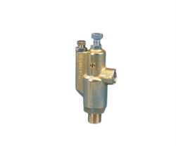
For high-demand applications requiring instantaneous pressure response, consider the Pratissoli AUTOMATIC PRESS.REG. H288, which delivers 20 L/min at 280 bar with rapid response characteristics suitable for industrial hydraulic systems requiring precision pressure control across variable demand cycles.
Component Maintenance and Performance Optimization
Gas valve regulation systems degrade predictably. Understanding degradation patterns prevents emergency failures and extends component life.
Diaphragm and Seal Inspection
Every 18-24 months of continuous operation, schedule internal inspection of the regulator's diaphragm and seals. Diaphragm material—typically EPDM rubber or reinforced elastomers—becomes rigid with age and exposure to high temperatures. A rigid diaphragm cannot flex proportionally, causing hunting (hunting: oscillation between slightly open and slightly closed positions, manifesting as outlet pressure pulsation).
If your outlet pressure gauge shows oscillation of ±10 bar or greater at constant load, the diaphragm likely needs replacement. Do not ignore hunting—it stresses downstream equipment and accelerates downstream component wear.
Pilot Pressure Line Maintenance
Pilot lines are vulnerable to particulate accumulation because pilot flow rates are extremely low (typically 0.5-2 L/min). Even microscopic particles that would pass through main-line filters can block pilot orifices. Install a 10-micron pilot line filter upstream of your pilot pressure tap. Change this filter quarterly in dusty environments, semi-annually in clean facilities.
For systems using high-pressure hoses with fittings, such as Pratissoli High Pressure Sewer Cleaning Hoses with Long Life Complete Fittings, ensure fittings are rated for pilot pressure (typically 5-10 bar). Under-rated fittings may weep, creating a slow pressure loss that manifests as drift in outlet pressure.
Pressure Spring Calibration Verification
The regulator's internal spring determines setpoint. Springs lose tension gradually—approximately 3-5% per year under normal conditions, faster at elevated temperatures. This is why drift creeps upward: the spring weakens, requiring larger diaphragm deflection to achieve pilot pressure feedback balance.
Your facility should measure actual outlet pressure monthly and compare to recorded setpoint. If outlet pressure has increased 15+ bar over 12 months, the spring requires replacement or the entire regulator must be exchanged. Attempting to adjust a weakened spring by turning external adjustment screws is temporary; it doesn't restore the spring's stability.
Advanced Diagnostics: Root Cause Analysis for Chronic Pressure Issues
Some pressure problems resist standard troubleshooting. These require systematic elimination.
Scenario 1: Outlet Pressure Instability During Demand Surges
When demand suddenly increases (load stepping from 25% to 100%), outlet pressure should dip momentarily, then recover within 2 seconds. If recovery takes 10+ seconds, the regulator is undersized or the sensing line has excessive volume. High sensing line volume (>500 mL) creates lag in pressure feedback to the diaphragm.
Solution: Reduce sensing line length or diameter. A 6mm sensing line is preferred over 12mm for systems under 100 bar. For high-pressure applications using pump discharge valves such as Pratissoli R1X/200 VALVE rated for 200 bar and 110 L/min, use rigid copper tubing rather than hose to minimize volume and lag.
Scenario 2: Creeping Outlet Pressure (Drift Upward)
This indicates internal leakage past the main poppet (the internal valve element). As the poppet wears, it seals less effectively, allowing more inlet pressure to reach the outlet without proportional diaphragm adjustment. The regulator compensates by opening less, effectively raising setpoint.
Diagnostic test: With system at rest (zero flow), block the outlet and monitor outlet pressure. If pressure climbs 20+ bar in 5 minutes with zero flow, internal leakage is severe. The poppet requires replacement or the entire regulator requires exchange.
Scenario 3: Sluggish Pressure Response (Slow Opening)
The regulator opens very slowly when demand increases, causing temporary low-pressure conditions downstream. This typically results from a partially blocked pilot line or a pilot pressure regulator set too low.
Diagnostic test: Measure pilot pressure while the system is under load. Pilot pressure should be 5-15% of outlet setpoint. If pilot pressure is zero or extremely low, the pilot line is blocked or the pilot regulator is faulty. Use nitrogen backflush (low pressure, 2-3 bar) to clear pilot lines.
For applications requiring guaranteed pilot pressure stability with high flow demands, the Pratissoli PUMP SRS65 1800 VER V 400V-AC pump valve delivers precise 6 L/min flow at 170 bar with pilot control suitable for systems where pilot reliability is critical to main valve performance.
Integration with 3G Electric's Industrial Equipment Support
With 35+ years of experience as a global distributor, 3G Electric provides not just components, but system-level expertise. Our technical team regularly fields questions from plant managers across diverse industries—oil refining, chemical processing, power generation, and manufacturing. The diagnostic protocols outlined in this guide reflect real-world troubleshooting patterns we've observed across thousands of installations.
When your facility encounters pressure regulation issues that resist standard troubleshooting, our team can provide remote diagnostic consultation. Provide photos of your gauge readings, system schematics, and timeline of pressure changes. We can recommend specific products like Pratissoli High Pressure Pilotflex 120 Hoses with Complete Fittings for replacing aging hose assemblies, or direct you toward component replacement strategies.
Regulation system optimization is not a one-time project—it's continuous refinement. Systems that operated reliably five years ago may require component updates as industrial standards evolve and original equipment ages. 3G Electric maintains current inventory of Pratissoli regulation components, pump discharge valves, and pressure control devices, enabling rapid sourcing when your diagnostic reveals component replacement needs.