Ignition and Fuel System Integration Troubleshooting: Industry Applications for Southeast Asian Industrial Operations
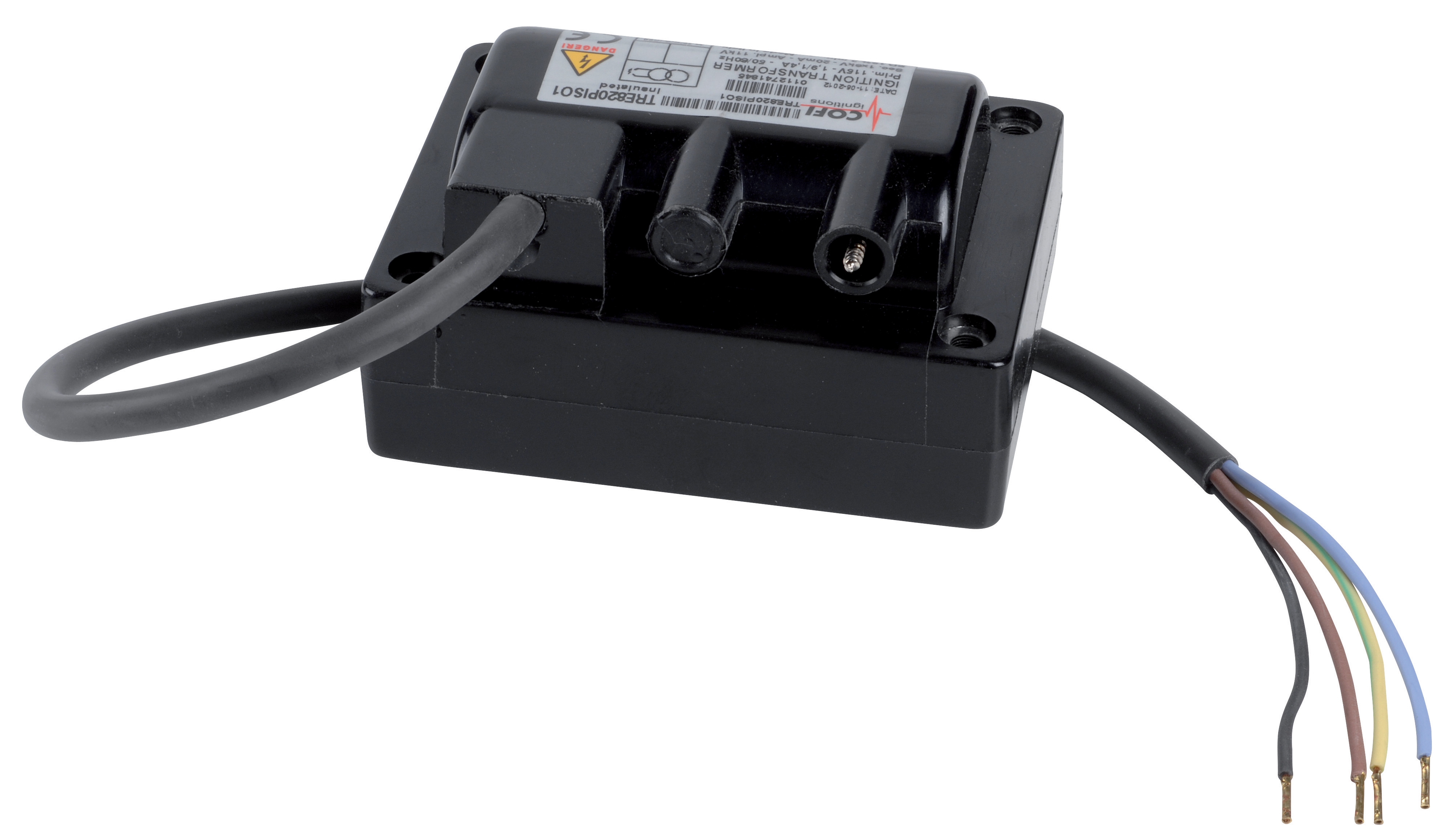
Table of Contentsexpand_more
Understanding Ignition System Architecture in Southeast Asian Industrial Applications
Industry Applications requiring reliable combustion depend on integrated ignition and fuel delivery systems that operate across diverse Southeast Asian climates and facility configurations. Over 35 years as an industrial equipment distributor, 3G Electric has observed that ignition system failures typically involve three interdependent subsystems: the ignition transformer, the fuel atomization nozzle, and the pressure regulation assembly.
The Cofi TRE 820 Piso1 ignition transformer represents a critical component in this architecture, converting 115 V primary input to 8000 V output required for reliable spark generation. However, this transformer operates across ambient temperatures ranging from −20 to 85 °C—a range that Southeast Asian facilities frequently exceed in outdoor combustion installations. When transformer output degrades, combustion becomes unstable, leading to premature burner shutdowns and production losses.
Integrating this transformer with pressure-regulated fuel delivery and precision spray nozzles requires understanding how electrical output, fuel pressure, and atomization patterns interact. Procurement engineers must diagnose failures systematically rather than replacing entire subsystems when targeted component replacement resolves the issue.
Diagnostic Procedures for Ignition Transformer Performance
Output Voltage Testing and Environmental Factors
The Cofi TRE 820 Piso1 is rated for 20 mA output at 8000 V, with molded cable construction rated for −20 to 85 °C operation. However, Southeast Asian industrial facilities frequently operate above these ambient specifications when equipment sits near burner exhaust zones or in unventilated equipment enclosures.
Diagnostic Procedure:
1. Verify input voltage stability: Using a true RMS multimeter, confirm that primary input voltage remains within ±10% of 115 V nominal. Southeast Asian power infrastructure occasionally experiences voltage fluctuations exceeding 15%, which degrades transformer secondary output even when primary voltage appears adequate on analog meters.
2. Measure secondary output under no-load conditions: With the burner system de-energized and disconnected from the transformer output, measure voltage at the secondary terminals. Output should read 7600–8400 V. Output below 7200 V indicates transformer core saturation or winding degradation.
3. Document ambient temperature during testing: Record facility temperature using a calibrated thermometer. If ambient exceeds 65 °C during operation, thermal cycling degrades transformer insulation faster than design specifications predict. This is particularly critical in Southeast Asian facilities where outdoor installations experience 50+ °C daily temperature swings.
4. Check molded cable integrity: Inspect the 380–440 mm molded cable for cracks, discoloration, or brittleness. In high-humidity Southeast Asian environments, inadequate cable strain relief accelerates insulation degradation. If cracks appear near the connector, replacement is mandatory—partial insulation failure creates shock hazards and unpredictable output voltage variation.
5. Perform load testing: Connect an approved spark gap tester (typically 6–8 mm gap) to secondary terminals. The transformer should reliably ignite the gap at least 50 consecutive times. Failure to ignite reliably after 15–20 iterations indicates output degradation below functional levels.
When output voltage reads below 7200 V or load testing fails intermittently, transformer replacement is required. Attempting to compensate with higher primary voltage damages the transformer faster and creates electrical safety risks.
Frequency and Waveform Considerations
The Cofi TRE 820 Piso1 operates across 50/60 Hz input frequencies. Southeast Asian facilities operate primarily on 50 Hz systems, but some industrial parks feature 60 Hz zones for compatibility with imported machinery. Mismatched frequency operation degrades transformer efficiency and output consistency.
Diagnostic Procedure:
- Use a frequency counter or digital oscilloscope to confirm facility power frequency matches transformer specification (50 Hz for most Southeast Asian locations).
- If frequency verification shows 50 Hz but ignition performance degrades during specific production cycles, check whether temporary 60 Hz generators power the ignition circuit during equipment maintenance or power outages. Transformer output degrades noticeably within 2–3 minutes of 60 Hz operation on 50 Hz-rated equipment.
Integrating Fuel Delivery with Ignition System Performance
Ignition system reliability cannot be assessed in isolation. The CBM Fluidics 1.35 45° SF spray nozzle delivers 1.35 L/h at 10 bar with a 45° spray angle, and this atomization pattern directly influences ignition reliability. When fuel atomization patterns degrade or pressure regulation inconsistencies occur, the ignition transformer must operate at peak output levels to achieve reliable combustion. This accelerates transformer degradation.
Nozzle Performance Verification
Diagnostic Procedure:
1. Establish baseline spray pattern: With the system operating at normal combustion temperature and pressure (10 bar nominal), observe the spray pattern visually or with high-speed photography. The 45° spray angle should produce a symmetrical cone with fine mist characteristics. Dropout of material outside the primary cone indicates nozzle orifice erosion.
2. Measure actual flow rate: Over 60 seconds of operation, collect fuel spray into a calibrated container and verify flow rate equals 1.35 L/h ±10%. Flow rate below 1.22 L/h indicates internal nozzle degradation and requires replacement. Southeast Asian fuels frequently contain higher water content and particulates than temperate-region specifications, accelerating orifice erosion.
3. Compare ignition success rates before and after nozzle replacement: Document the number of spark attempts required for reliable flame establishment at standard operating pressure. If replacement nozzles reduce required spark attempts by 30% or more, the original nozzle degradation was forcing the ignition transformer to operate beyond optimal load conditions.
Pressure Regulation Consistency
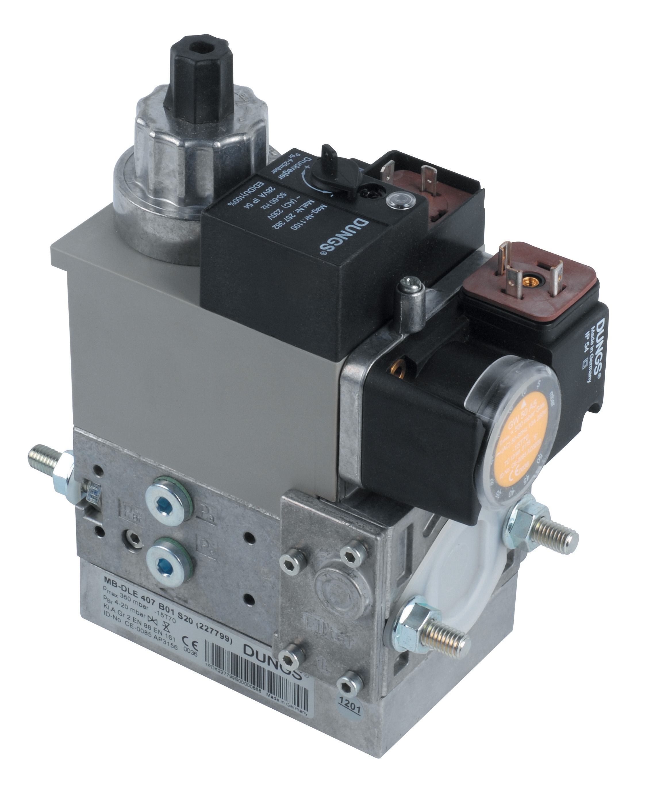
The Francel B25/37mb pressure regulator with integrated safety relief maintains 37 mbar outlet pressure for applications requiring precise fuel control. However, fuel delivery systems serving combustion burners typically operate at higher pressures (8–15 bar) using different regulating valves. When 37 mbar regulators appear in fuel supply circuits, they indicate either:
1. Gas fuel (natural gas or propane) systems where lower pressure regulation is appropriate
2. Mis-specified components creating system incompatibility
Diagnostic Procedure for Fuel Pressure Systems:
- Install calibrated pressure gauges at three measurement points: fuel supply inlet, post-regulator outlet, and fuel nozzle inlet.
- Record pressure readings over a 10-minute operating cycle. Pressure should remain within ±0.5 bar of setpoint throughout operation.
- If pressure at the nozzle inlet fluctuates ±2 bar or more during steady-state operation, the regulating valve is undersized or degraded. This creates spray pattern inconsistency that forces the ignition transformer to compensate with increased spark frequency.
- Southeast Asian humid environments promote corrosion of valve trim and seals. If facility air compressors lack proper desiccation systems, moisture ingress into fuel regulators occurs within 3–6 months, degrading pressure control.
System-Level Troubleshooting for Complete Combustion Circuits
Pressure Regulation in Pump-Driven Systems
When industrial applications require robust fuel or hydraulic delivery, the Pratissoli KF30 high-performance industrial pump delivers 106 L/min flow at 200 bar pressure. The Pratissoli R1/400 regulating valve maintains system pressure stability across varying load conditions, rated to 400 bar with 110 L/min flow capacity.
These components are designed for hydraulic and industrial fluid delivery systems, not ignition fuel circuits. However, procurement engineers sometimes specify these components in large-scale combustion installations where fuel delivery rates exceed 100 L/min. Understanding their behavior prevents system integration failures.
Diagnostic Procedure:
1. Verify regulator setpoint accuracy: Adjust the Pratissoli R1/400 regulating valve to target system pressure and record the actual outlet pressure under full flow conditions (110 L/min). If actual pressure deviates more than ±5 bar from setpoint, the valve requires servicing or replacement.
2. Observe pressure stability during transient load changes: Reduce pump flow by 50% (from 106 L/min to 53 L/min) and record pressure response time. The regulator should achieve new steady-state pressure within 2 seconds. If pressure overshoots by more than 10 bar before stabilizing, damping elements inside the regulator are degraded.
3. Check for internal leakage: With the pump operating at setpoint pressure with no external load, measure leakage flow from the regulator's drain port over 60 seconds. Internal leakage exceeding 5 L/min (for a 110 L/min capacity valve) indicates seal degradation requiring valve replacement.
Integration Testing Across Subsystems
Once individual components perform within specification, test the complete system before production deployment:
1. Establish baseline operating parameters: Record ignition success rate, fuel pressure stability, spray pattern symmetry, and burner flame appearance during normal operation over 30 minutes. Document these baselines before component replacement for post-maintenance comparison.
2. Monitor ignition spark timing relative to fuel delivery: Using oscilloscope analysis or burner control system diagnostics, confirm that spark ignition occurs within 500 milliseconds of fuel delivery initiation. Longer delays indicate either transformer output degradation or fuel atomization delays caused by pressure regulation inconsistency.
3. Perform thermal cycle testing: In Southeast Asian climates, facilities may experience 40+ °C temperature swings between night and day operation. Run the complete system through several operating cycles spanning a 24-hour period and document performance drift. If ignition reliability degrades during peak afternoon temperatures, thermal sensitivity in transformer or regulator components requires addressing through specification of components with extended temperature ratings.
Procurement Specifications for Reliable Southeast Asian Operations
Based on 35+ years of experience distributing industrial equipment across regional markets, 3G Electric recommends the following procurement practices:
1. Specify components with extended ambient temperature ratings when outdoor installation or proximity to heat sources is anticipated. The Cofi TRE 820 Piso1 transformer is rated to 85 °C, but Southeast Asian installations frequently exceed this. Request supplier confirmation of performance at 100+ °C or specify thermal derating in performance specifications.
2. Include humidity and corrosion resistance requirements in procurement specifications. Southeast Asian coastal facilities and high-humidity inland regions accelerate corrosion of regulator trim, seal materials, and transformer insulation. Request stainless steel construction for fuel regulators and specify corrosion-resistant terminal connections for ignition transformers.
3. Implement preventive maintenance intervals of 6 months for fuel delivery components and 12 months for ignition transformers in Southeast Asian applications. This exceeds typical temperate-region recommendations but reflects accelerated aging in tropical climates.
4. Maintain spare components inventory for critical ignition and fuel regulation subsystems. Supply chain delays for specialized industrial components frequently extend 4–8 weeks across Southeast Asia. Maintaining Cofi TRE 820 Piso1 transformers and CBM Fluidics spray nozzles in inventory prevents extended facility shutdowns during component failures.