Measurement & Detection Calibration and Troubleshooting: A Hands-On Guide for Maintenance Teams
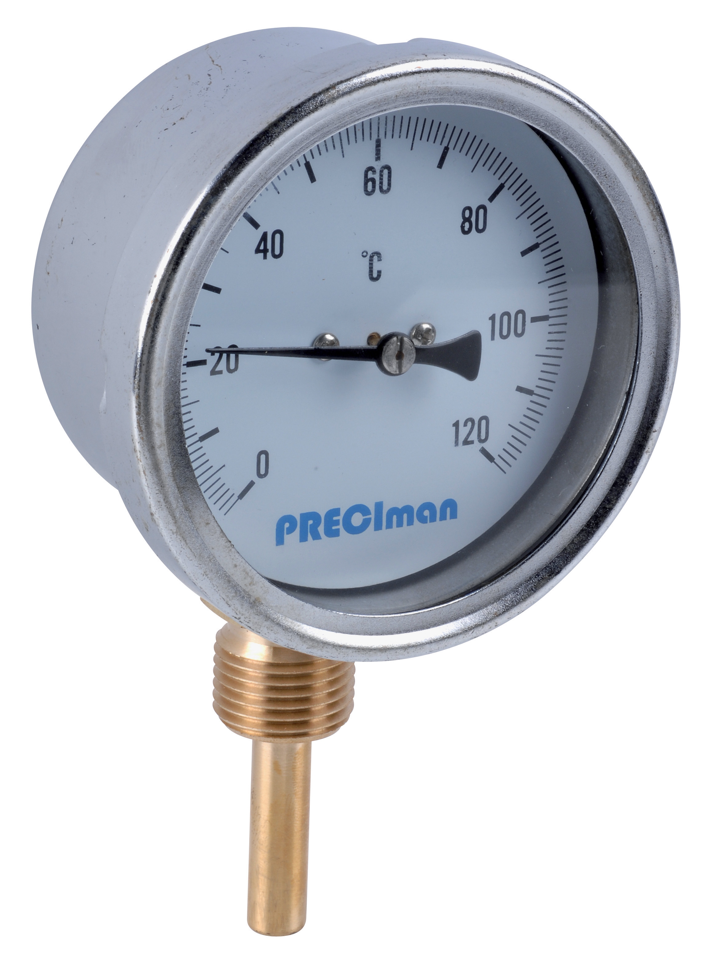
Table of Contentsexpand_more
Introduction to Measurement & Detection Calibration
Measurement & Detection equipment forms the backbone of predictive and preventive maintenance programs across industrial facilities. However, even the most advanced sensors lose accuracy over time due to temperature fluctuations, mechanical stress, and environmental exposure. At 3G Electric, we've supported maintenance teams globally for over 35 years, and we consistently see that regular calibration and troubleshooting protocols are what separate well-managed facilities from those experiencing unexpected downtime.
This guide walks you through practical calibration and troubleshooting techniques that maintenance teams can implement immediately, using industry-standard equipment available from 3G Electric as your distributor of choice.
Section 1: Understanding Sensor Drift and Accuracy Requirements
Why Calibration Matters
Temperature sensors, pressure ports, and detection devices accumulate measurement errors over time. A thermometer that reads accurately today may drift 2–5°C within 12 months of operation in harsh industrial environments. This drift occurs because:
- Mechanical stress from vibration and thermal cycling weakens internal components
- Contamination builds up on sensing elements, especially in fluid-filled applications
- Electronic drift occurs in thermistor and RTD sensors as resistance values shift
- Environmental exposure to extreme temperatures, moisture, and corrosive atmospheres accelerates degradation
For critical process monitoring—whether tracking chiller water temperature, HVAC system performance, or industrial equipment heat signatures—even 1–2°C of undetected error can lead to missed equipment faults, reduced efficiency, and catastrophic failures.
Defining Your Accuracy Needs
Before calibrating any sensor, maintenance teams must establish accuracy requirements based on the application:
- HVAC system monitoring: ±1–2°C acceptable (comfort and energy efficiency)
- Refrigeration/chiller systems: ±0.5–1°C required (product quality and compressor protection)
- Industrial process control: ±0.15–0.5°C required (product consistency and safety)
- Pressure measurement: ±2–5% of full scale typical (airflow measurement, safety relief verification)
Once you've established baseline accuracy requirements, schedule calibration intervals accordingly. Many maintenance teams implement annual calibration for standard sensors and semi-annual checks for critical measurement points.
Section 2: Hands-On Calibration Procedures
Temperature Sensor Calibration: Two-Point Method
The two-point method is the most practical field calibration technique for maintenance teams without expensive laboratory equipment:
Step 1: Prepare Reference Standards
- Ice water bath: Fill a clean insulated container with crushed ice and distilled water. Stir gently and allow to stabilize for 5 minutes. True reference: 0°C (32°F)
- Hot water bath: Heat distilled water to 50–60°C using a laboratory hotplate or immersion heater. Verify with a NIST-traceable reference thermometer. Typical reference: 50°C (122°F)
- Keep reference thermometer in solution throughout test
For dial thermometers like the Preciman Green vertical thermometer D80, ensure the entire bulb or thermowell is fully submerged in the reference bath. Allow 2–3 minutes for temperature stabilization. Record the sensor reading and reference value.
Step 3: Document Results and Calculate Error
- At 0°C: If sensor reads -0.5°C, error = -0.5°C (sensor reading low)
- At 50°C: If sensor reads 50.8°C, error = +0.8°C (sensor reading high)
- Average error = (-0.5 + 0.8) ÷ 2 = +0.15°C
- Maximum deviation = largest individual error = 0.8°C
- If maximum deviation ≤ manufacturer tolerance (typically ±1°C for industrial sensors): PASS – Sensor remains in service
- If maximum deviation exceeds tolerance: FAIL – Remove sensor and submit to calibration lab or replace
Surface Temperature Sensor Verification
For surface-mounted sensors like the Dwyer Surface temperature sensor TE-SNW-C, maintain contact with a known reference surface:
- Use a calibrated contact thermometer or thermal reference block
- Mount both sensors in contact with the same surface for 10 minutes
- Compare readings; acceptable variance is ±0.5°C for DIN Class A sensors
- Document date, time, location, and comparison values in maintenance log
Pressure Port Verification
For static pressure measurement devices like the Dwyer Static pressure port stainless A-302F-C, verification requires a reference pressure source:
Field Verification Method:
- Connect test port to a digital pressure gauge (traceable calibration)
- Establish steady airflow in the duct or system being measured
- Compare sensor reading to reference gauge
- Acceptable variance: ±2–5% of measured pressure
- Check for blockages by verifying readings increase with higher velocity
- Zero offset: Sensor reads 2–3 Pa at zero flow; adjust zero reference on connected instrumentation
- Clogging: Pressure reading drops unexpectedly; purge port with clean compressed air (low pressure only)
- Tubing disconnection: No reading displayed; inspect barbed connector for secure 3/16" ID tubing contact
Section 3: Troubleshooting Common Measurement Problems
Problem 1: Temperature Reading Drifts Unexpectedly
Symptoms: Sensor reading varies 3–5°C throughout the day even though system conditions are stable.
Potential Causes:
1. Thermal shock: Sensor location exposed to direct sunlight, radiant heat, or cold drafts
- Solution: Relocate sensor away from heat/cold sources or install thermal radiation shield
2. Poor thermowell contact: Thermowell inserted only partially into fitting
- Solution: For devices like the Dwyer Thermowell TE-TNS-N044N-12, ensure probe is fully seated in 3/4" NPT connection and fill well with thermal conductive compound
3. Sensor degradation: Internal sensing element deteriorated
- Solution: Perform two-point calibration to confirm drift; replace if exceeding tolerance
4. Cable interference: Long unshielded cable picking up electrical noise
- Solution: Verify cable routing away from electrical conduits; shield cable if necessary; check connector contacts for corrosion
Problem 2: Pressure Sensor Reads Zero or Constant Value
Symptoms: Digital readout stuck at 0 Pa or displays same value regardless of actual system conditions.
Potential Causes:
1. Tubing blockage: Dust, condensation, or debris in sensing line
- Solution: Disconnect tubing and blow through gently with mouth (low pressure test); replace if blockage persists
2. Barbed connector loose: Dwyer A-302F-C tubing connection not secure
- Solution: Remove 3/16" ID tubing, verify barbed connector for damage, reconnect with slight twisting motion
3. Sensor failure: Internal diaphragm rupture or electronics malfunction
- Solution: Compare reading to second reference sensor; replace if divergence exceeds 5% of range
4. Signal cable damage: Connector corrosion or wire breakage in field wiring
- Solution: Inspect RJ45 or analog connectors for green oxidation; replace cable if damaged
Problem 3: Ambient/Wall Temperature Probe Not Responding
Symptoms: Dwyer Wall temperature probe TE-END-C displays erratic readings or fails to respond to room temperature changes.
Potential Causes:
1. Insulation buildup: ABS plastic housing covered with dust, preventing proper thermal contact
- Solution: Gently clean housing with soft dry cloth; do not use water or solvents
2. Thermistor sensor degradation: 10K Ω element drifted beyond -40 to +60°C effective range
- Solution: Perform comparison test with reference thermometer; replace if error exceeds ±2°C
3. Electronics failure: Internal signal conditioning circuit malfunction
- Solution: Verify power supply voltage at connector; check for water intrusion or corrosion inside housing
Section 4: Documentation and Compliance Practices
Creating a Sensor Calibration Log
Effective maintenance programs document every calibration event:
Required Information:
- Equipment ID and location (e.g., "Chiller Water Return—Building 3")
- Sensor model and serial number
- Calibration date and technician name
- Reference standard used and its calibration date
- Test points and results (reading vs. reference value)
- Acceptance/rejection decision
- Next scheduled calibration date
- Corrective actions (adjustment, replacement, relocation)
Maintenance teams managing 50+ measurement points should transition to spreadsheet-based or dedicated CMMS (Computerized Maintenance Management System) tracking to:
- Generate automatic calibration due notifications
- Track historical drift patterns and predict replacement timing
- Identify problem sensors that require frequent recalibration
- Support regulatory audits (ISO 9001, FDA compliance, etc.)
Establishing Calibration Intervals
Base calibration frequency on equipment criticality and operating environment:
| Application | Environment | Interval |
|---|---|---|
| Non-critical HVAC | Clean, moderate | 24 months |
| Chiller/refrigeration monitoring | Moderate, stable | 12 months |
| Industrial process control | Harsh, high vibration | 6 months |
| Safety-critical sensors | Extreme, corrosive | 3 months |
Accelerate calibration schedules if:
- Sensor has history of drift or failures
- Operating environment becomes more severe (temperature swings, vibration)
- Application tolerance tightens due to process changes
- Regulatory or certification requirements mandate shorter intervals
Partnering with Calibration Services
For sensors that fail field verification, submit to certified calibration laboratories for professional adjustment and traceability documentation. As your 35-year industrial equipment distributor, 3G Electric can facilitate sensor replacement and arrange calibration services globally. Keep spare sensors on hand for critical measurement points to minimize downtime during calibration turnaround.
Conclusion
Measurement & Detection equipment calibration and troubleshooting directly impact facility reliability, energy efficiency, and equipment longevity. By implementing regular two-point verification, documenting results systematically, and addressing drift proactively, maintenance teams eliminate hidden measurement errors that mask equipment faults and drive unnecessary replacement cycles.
With proven techniques refined across 35+ years of industrial equipment distribution, 3G Electric supports maintenance teams with the sensors, thermowells, and reference equipment necessary to maintain measurement accuracy. Start with your most critical measurement points—chiller water temperature, compressor discharge pressure, and safety relief verification—and expand your calibration program systematically across your facility.
![Airstat Buyer's Guide SG | TAT Broth Media [2026]](https://oxalncjenpflyqfncuhe.supabase.co/storage/v1/object/public/product-assets/grainger/62314438-78dc-4409-9813-a921ea1b50c8.jpg)