Measurement & Detection in Commissioning and Calibration: Ensuring Accuracy Across Industrial Systems
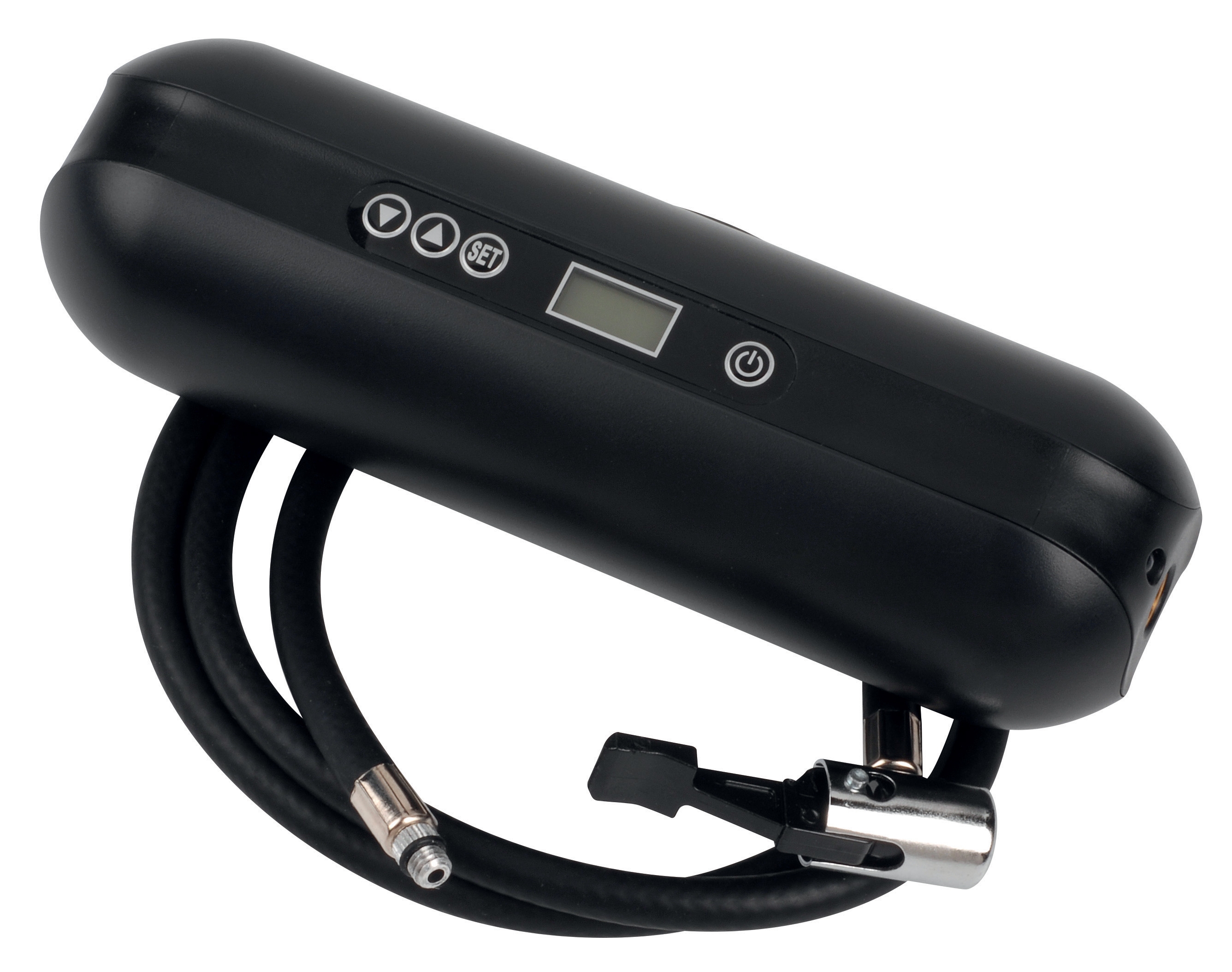
Table of Contentsexpand_more
Understanding Measurement & Detection in Commissioning Workflows
Measurement & Detection equipment forms the backbone of industrial system commissioning. When new systems are installed or existing equipment undergoes major maintenance, accurate commissioning ensures that all sensors, transmitters, and gauges operate within specification before the system goes live. For maintenance teams, the commissioning phase is where you establish baseline data, verify sensor response, and confirm that detection thresholds are correctly configured.
With over 35 years of experience supplying industrial equipment across Asia-Pacific, 3G Electric has seen how critical this phase is. A poorly commissioned system may appear to function normally but deliver inaccurate readings that compound over time, leading to inefficient operation, missed alarms, or safety risks.
Commissioning involves three core activities: zero-point verification, span calibration, and sensor response testing. Each requires specific tools, documented procedures, and an understanding of acceptable tolerance ranges. Unlike ongoing monitoring or preventive maintenance, commissioning is a one-time verification that establishes confidence in your measurement systems before they enter service.
Zero-Point Verification and Baseline Establishment
Zero-point verification confirms that your measurement device reads correctly when exposed to a known reference condition. For pressure transmitters like the Dwyer 616KD-13V-TC, this means isolating the sensor and measuring its output under atmospheric pressure or vacuum conditions, depending on the sensor type.
For temperature probes such as the Dwyer PT100 OHM RTD, zero-point verification involves comparing the probe's resistance output against a calibrated reference thermometer in an ice bath (0°C) or boiling water (100°C). The Dwyer probe operates with ±0.6% accuracy at 0°C, meaning you should document the actual reading and compare it against expected values.
In practice, here's what your team should do:
- Prepare a controlled environment: Use a stable temperature bath or pressure source. For temperature work, an ice bath costs nothing and provides reliable 0°C reference.
- Connect your reference instrument: Place your calibrated reference (thermometer, pressure gauge, multimeter) alongside the sensor being commissioned.
- Record baseline data: Take at least three readings over 2–3 minutes to ensure stability. Document the time, ambient conditions, and readings.
- Compare against specification: Check your equipment datasheet. The Dwyer PT100 probe should be within ±0.6% of the reference value. For pressure devices, tolerance is typically ±1–2% of full scale.
- Document the result: Keep commissioning records. If zero-point is outside tolerance, the device may require factory calibration before deployment.
Zero-point verification is not a one-step test. Perform it at the start of commissioning, again mid-way through testing, and once more before sign-off. Drift indicates potential issues with wiring, connector corrosion, or sensor problems.
Span Calibration and Multi-Point Verification
Span calibration verifies that your sensor reads accurately across its operating range, not just at zero. A pressure gauge with a 0–40 mbar range (such as the Preciman stainless steel vertical gauge) must be tested at multiple points: 0 mbar, 10 mbar (25%), 20 mbar (50%), 30 mbar (75%), and 40 mbar (100%).
Multi-point calibration catches non-linearity issues. Some sensors read accurately in the middle of their range but drift at the extremes. For HVAC applications, you may only use 10–30% of a gauge's full-scale range during normal operation, so verify accuracy in that band specifically.
Practical commissioning steps for span verification:
1. Establish a calibrated pressure or temperature source: Use a portable calibrator, deadweight tester, or precision reference device. These are available through 3G Electric and are essential commissioning tools.
2. Test at 0%, 25%, 50%, 75%, and 100% of range: For the Preciman gauge rated 0–40 mbar, test at 0, 10, 20, 30, and 40 mbar.
3. Record deviation at each point: Compare sensor reading to reference reading. Calculate percentage error: (Sensor Reading - Reference Reading) / Full Scale Range × 100%.
4. Accept or reject based on tolerance: The Preciman gauge is rated ±1.6% accuracy. At 40 mbar full scale, maximum acceptable error is 0.64 mbar. If your readings exceed this at any point, escalate for factory calibration.
5. Test in operating orientation: Pressure gauges give different readings if tilted. Commission the Preciman gauge in its final installed orientation (vertical, in this case).
6. Repeat after temperature stabilization: If temperature changed during testing, retest. Sensor output drifts with temperature, especially for resistance-based devices like the Dwyer PT100.
For differential pressure transmitters like the Dwyer 616KD-13V-TC measuring 0–1 IN W.C., apply positive and negative pressure (relative to atmosphere) and verify linearity. Many HVAC systems measure across only 0.1–0.5 IN W.C., so focus your multi-point test on that range.
Sensor Response Testing and System Integration
Once individual sensors are commissioned, you must verify that they respond correctly within the installed system. A pressure transmitter may read accurately in isolation but fail if its impulse lines are kinked, contain water, or are connected to the wrong port.
System-level response testing includes:
- Impulse line integrity: For the Dwyer transmitter with barbed connections, ensure tubing is routed without sharp bends, traps, or dead legs. Trapped water or air causes sluggish response and inaccuracy. Commission by applying known pressure and observing response time. Expect electronic transmitters to respond within 1–2 seconds.
- Sensor isolation testing: Using the CBM expansion tank inflator, apply known pressure to expansion tank systems and confirm that connected pressure transmitters read the correct value. The inflator's 10.3 bar maximum helps commission systems across the full rated range.
- Cross-sensor verification: If your system has multiple pressure or temperature sensors, commission them simultaneously and compare readings. In an HVAC loop with flow measurement via the Dwyer MAFS-16 flow probe, verify that differential pressure, static pressure, and total pressure readings are self-consistent. For a 16 cm probe in duct flow, differential pressure should follow the square law: higher flow = higher pressure drop.
- Alarm and setpoint testing: After commissioning individual sensors, test alarm outputs. Slowly increase pressure past the high-alarm setpoint and confirm that the alarm triggers. Similarly, decrease pressure below the low-alarm setpoint. Document the actual trigger points; they may not align exactly with programmed setpoints due to transmitter hysteresis.
- Output range verification: The Dwyer 616KD-13V-TC outputs 4–20 mA signal. Confirm that 4 mA corresponds to 0 IN W.C. and 20 mA corresponds to 1 IN W.C. Use a multimeter to measure output current at 0%, 50%, and 100% of range.
System integration testing reveals wiring errors, signal noise, and installation defects that zero-point and span tests cannot catch. A sensor may be individually accurate but produce noisy readings if the transmitter is located near variable frequency drives or high-voltage equipment. In such cases, commission by documenting the noise level, updating control system filtering parameters, and re-testing after system startup.
Documentation, Tolerance Records, and Handover
Commissioning is incomplete without documentation. Maintenance teams must hand over systems with commissioning certificates that prove sensors were verified and perform within specification.
Essential commissioning documentation includes:
- Equipment identification: Serial numbers, model numbers (e.g., DWY04218, ROS20004, DWY28014), and installation location.
- Test dates and personnel: Who performed the test, when, and under what conditions.
- Zero-point test results: Reference readings and sensor readings at baseline condition.
- Span test results: Multi-point calibration data at 0%, 25%, 50%, 75%, 100% of range, including percentage error at each point.
- Tolerance acceptance criteria: State the allowed error (e.g., ±1.6% for the Preciman gauge) and confirm all readings meet this requirement.
- System response test results: Response time, impulse line checks, cross-sensor comparisons, alarm trigger points, and output range verification.
- As-left configuration: Document all sensor locations, orientation, calibration trimming adjustments (if any), and setpoint programming in the control system.
- Outstanding items: If any item failed commissioning and requires factory calibration or component replacement, list it and confirm rework completion before system handover.
For expansion tank systems using the CBM inflator operating at -20 to 60°C, include ambient temperature limits in your commissioning record. If the system will operate near temperature extremes, commission at the upper and lower bounds and document temperature-related drift.
Hand over commissioning records to the facility operations team. These records serve as baseline data for future troubleshooting. When a sensor fails or drifts years later, you can compare current readings against commissioning baselines to determine degradation rate and remaining useful life.
Why Commissioning Matters for Maintenance Teams
Commissioning is not a bureaucratic box-tick exercise. It is the foundation of accurate maintenance diagnostics. When you later suspect a sensor is giving wrong readings, commissioning data lets you quickly determine whether the sensor has degraded or whether the problem lies elsewhere (wiring, calibration drift, installation change).
Without proper commissioning, you have no baseline. A transmitter reading 0.8 IN W.C. may be accurate, or it may have drifted 0.3 IN W.C. since installation—you simply do not know. This uncertainty cascades: you over-cool or under-heat spaces, miss real faults while chasing phantom problems, and lose confidence in your sensors.
3G Electric supports commissioning through supply of calibrated reference equipment and high-accuracy sensors like the Dwyer PT100 probe and Dwyer transmitter. Our team can advise on commissioning procedures during equipment selection, ensuring you choose sensors with the precision your application demands.
Take commissioning seriously, document thoroughly, and your maintenance team will operate with clarity and confidence for years to come.
![Airstat Buyer's Guide SG | TAT Broth Media [2026]](https://oxalncjenpflyqfncuhe.supabase.co/storage/v1/object/public/product-assets/grainger/62314438-78dc-4409-9813-a921ea1b50c8.jpg)