
Pumps & Compressors: Installation Integration and System Commissioning for HVAC Contractors in Singapore
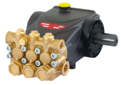
Table of Contentsexpand_more
Understanding Pumps & Compressors in Modern HVAC Systems
Pumps & Compressors form the circulatory backbone of HVAC systems, managing refrigerant flow, chilled water distribution, and pressure regulation across complex installations. For HVAC contractors in Singapore's hot, humid climate, proper commissioning directly impacts system longevity, efficiency ratings, and warranty compliance.
With over 35 years of industrial equipment distribution experience, 3G Electric understands that premature failures typically stem not from component defects, but from improper installation and commissioning practices. This guide addresses the critical integration phase often overlooked in contractor workflows—the period between equipment delivery and operational handover.
Pre-Installation Planning and System Assessment
Hydraulic and Refrigerant Circuit Analysis
Before any pump or compressor enters your system, conduct a detailed circuit analysis:
Flow Rate Matching: Calculate actual system demand against pump displacement. For instance, the Pratissoli KF30 delivers 106 L/min at 200 bar with 40 kW input. If your chilled water loop requires only 80 L/min, oversizing creates unnecessary energy consumption and valve stress. Document required flow at design delta-T conditions.
Pressure Drop Calculations: Map every component in the circuit—coils, filters, valves, distribution manifolds. Sum total pressure drops and add 15% safety margin. The Interpump E2C2111 L rated at 210 bar suits high-pressure hydraulic applications but may be excessive for standard chilled water systems operating at 35 bar.
Fluid Compatibility Verification: Confirm pump construction materials against system fluid specifications. Interpump ATEX-rated units like the W2035 L ATEX (35 L/min, 200 bar) suit hazardous environment applications with specific oil requirements, while standard models accept broader fluid ranges.
Mounting and Vibration Isolation
Improper mounting causes cascading failures within weeks:
- Foundation Analysis: Specify concrete pad dimensions based on pump weight. The Interpump SSU2040 R ATEX weighs 21 kg; undersized pads permit movement during operation
- Isolation Mounts: Use elastomeric or spring isolators rated for 2–3× actual dynamic load. Vibration frequency mismatch between pump (typically 1750 rpm fundamental) and building structure resonance amplifies oscillation
- Alignment Tolerance: Shaft misalignment exceeding ±0.05 mm causes bearing wear within 6 months. Use dial indicators during installation; never assume factory alignment remains after transport
- Suction Line Design: Keep suction line velocity below 1.2 m/s and install low-pressure drop strainers. Cavitation damage in centrifugal pump inlets occurs within hours of improper inlet design
Integration Protocols for Chilled Water and Refrigerant Systems
Piping Configuration and Flushing Procedures
System cleanliness determines component lifespan. Implement this flushing sequence before pump installation:
1. Preliminary Flush: Circulate clean water at design flow rate (no pump yet) through all piping, coils, and distribution branches for 48 hours. Document pressure and temperature stability
2. Strainer Inspection: Extract strainers every 24 hours; continue flushing until no particulate remains (ISO cleanliness target: 17/15/12)
3. Chemical Cleaning: For existing piping with iron oxide deposits, circulate approved alkaline cleaner (pH 9–11) for 72 hours at elevated temperature (50–60°C)
4. Passivation: For stainless steel components, apply light passivation solution to prevent corrosion initiation
5. Final Flush: Run deionized water for 24 hours before pump connection
Critical Detail: Shutdown procedures matter. Valve the pump outlet to bypass or reservoir before system depressurization. Sudden pressure drops cause fluid aeration and bearing damage.
Pump Connection and Priming
For positive displacement pumps like the Interpump E2C1714 (14 L/min, 170 bar):
- Suction Port Preparation: Install a foot valve on suction lines to maintain prime during idle periods. For 15–25 meter suction lifts, manual priming via top vent valve is required
- Pressure Relief Integration: Mount pilot-operated relief valves within 30 cm of pump discharge. Set relief pressure 10% above maximum system pressure (e.g., 154 bar for 140 bar operating pressure)
- Manifold Block Integration: Ensure manifold cavity volumes don't exceed pump displacement × 0.5 second cycle time—oversized cavities cause pressure oscillation and seal fatigue
- Bleeding Air: Run pump at 25% displacement for 5–10 minutes with discharge relief fully open. Listen for cavitation noise (typical grinding/crackling sound); continue bleeding until noise stops
Compressor Integration in Refrigerant Circuits
For HVAC contractors, compressor commissioning differs fundamentally from pump procedures:
- Evacuation Before Operation: Achieve 500 microns (0.5 mbar) vacuum before any refrigerant charge. Use certified recovery equipment and dual-stage vacuum pumps
- Oil Charge Verification: Total system oil volume must match compressor sump capacity plus 10%. Excess oil causes liquid slugging at startup; insufficient oil causes bearing starvation
- Superheat and Subcooling: Establish proper refrigerant charge by measuring superheat at compressor inlet (typically 8–15°C) and subcooling at condenser outlet (5–15°C). Mismatch indicates undercharge or valve blockage
- Soft Start Implementation: Use electronic soft starters or unloader valves for first-start ramp-up. Peak inrush current for 40 kW compressors approaches 120 A; soft starters limit this to 60–80 A
Commissioning Testing and Performance Validation
Startup Sequencing and Load Ramping
Structured startup prevents equipment damage and identifies integration faults early:
Phase 1: Dry Run (No Load)
- Start pump at zero system pressure with discharge relief fully open
- Run for 15 minutes; verify bearing temperature remains below 60°C
- Monitor inlet vacuum (should remain below 0.2 bar absolute)
- Check for unusual vibration or noise patterns
- Slowly close discharge relief valve in 10 bar increments
- Pause 5 minutes at each pressure step to assess thermal stability
- Monitor motor amperage; it should rise proportionally with pressure
- Stop immediately if amperage exceeds motor nameplate rating
- Establish system at 80% design pressure with relief closed
- Measure actual discharge flow with calibrated flowmeter
- Compare against pump specification (e.g., KF30 rated 106 L/min at 1750 rpm)
- Flow deviation exceeding ±5% indicates internal leakage or cavitation
Performance Documentation and Baseline Establishment
Create permanent commissioning records for warranty validation and future diagnostics:
Data Points to Record:
- Discharge pressure at 25%, 50%, 75%, 100% load steps
- Discharge temperature at each load point (expected rise: 3–8°C per 50 bar pressure increase)
- Motor current draw and power factor
- Vibration acceleration measured at pump housing (bearing frequency range: 100–500 Hz)
- Suction line vacuum and outlet backpressure
- Fluid analysis sample (viscosity, acid number, water content via Karl Fischer titration)
Thermal and Acoustic Commissioning
Singapore's ambient heat exacerbates thermal stress:
- Cooler/Heat Exchanger Sizing: Verify cooler capacity matches pump heat output at continuous duty. Heat generation (kW) ≈ (discharge pressure - suction pressure) × flow rate ÷ 600 × (1 - efficiency)
- Ambient Temperature Adjustment: For units in unconditioned equipment rooms (common in Singapore facilities), derate cooler capacity by 15–20%. High ambient reduces heat dissipation efficiency
- Acoustic Testing: Measure sound level at 1 meter distance. New pumps typically produce 78–85 dB(A); excessive noise (>90 dB) indicates misalignment, cavitation, or bearing wear—pause operation and investigate
- Hose and Manifold Vibration: Use vibration pen to confirm no structural resonance in piping. Hoses should remain free from visible oscillation during steady-state operation
Supply and Commissioning Support from 3G Electric
3G Electric stocks critical Pumps & Compressors for immediate Singapore delivery:
- Interpump E2C2111 L: Compact 11 L/min positive displacement pump for confined spaces and high-pressure hydraulic circuits
- Interpump W2035 L ATEX: 35 L/min ATEX-compliant pump for classified hazardous areas (refineries, chemical plants)
- Pratissoli KF30: High-flow Italian-engineered pump (106 L/min) for large-capacity chilled water systems
- Interpump SSU2040 R ATEX: 40 L/min gear pump rated for demanding industrial fluid transfer
- Interpump E2C1714: Compact 14 L/min pump for retrofit installations and secondary cooling loops
Our technical team provides commissioning consultation, pressure testing certification, and performance baseline documentation—essential for contractor warranty claims and system performance disputes.
![Oil Pump Singapore: Complete Buyer's Guide [2026]](https://oxalncjenpflyqfncuhe.supabase.co/storage/v1/object/public/product-assets/grainger/84612678-850d-43eb-92ae-dcc86df1619a.jpg)
![Dayton Centrifugal Pump SG | Sizing Guide [2026]](https://oxalncjenpflyqfncuhe.supabase.co/storage/v1/object/public/product-assets/grainger/21a225f1-43ff-4290-a467-4a8181c4501a.jpg)


