How to Diagnose and Troubleshoot Burner Control System Failures in Singapore
How to Diagnose and Troubleshoot Burner Control System Failures in Singapore
Burner control system failures represent one of the most costly operational disruptions in industrial heating applications. Whether you operate gas burners, oil burners, or dual-fuel systems across Singapore's manufacturing, food processing, or chemical industries, unexpected control failures can halt production and compromise safety. Unlike burner sizing or performance optimization—which are planned processes—troubleshooting demands a systematic diagnostic methodology to isolate root causes quickly and restore operation. This guide walks through the technical diagnosis procedures used by industrial professionals to resolve burner control faults, from flame detection sensor issues to safety lockout conditions, using proven diagnostic sequences and reference to industry-standard control components.
Understanding Burner Control System Architecture and Failure Modes
Modern burner control systems operate as integrated safety loops rather than simple on/off switches. The architecture comprises four primary functional layers: ignition and fuel supply sequencing, flame detection and confirmation, combustion parameter monitoring, and safety interlocking. Understanding this architecture is essential before diagnosing failures, because symptoms often manifest in one layer while root causes originate in another.
The ignition sequence typically energizes the fuel solenoid valve and ignition transformer in a controlled sequence, then monitors for flame presence within a defined proving period (usually 3-5 seconds). If flame is not detected during this window, the control enters a safety lockout state, disabling all fuel supply until manual reset occurs. This safety-critical design prevents accumulation of unburned fuel—a serious explosion hazard.
Flame detection itself uses one of three primary sensor types: photoresistive cells that change electrical resistance based on flame radiation, infrared detectors that respond specifically to heat signatures, and phototransistors that convert light into electrical current. Each sensor type has different spectral sensitivity, response time characteristics, and environmental tolerance ranges. Control relays interpret sensor signals and make binary decisions: flame present or absent.
Combustion parameter monitoring may include air pressure proving (for forced-draft burners), fuel pressure validation, and modulation feedback loops for systems equipped with proportional control capabilities. Each monitoring point represents a potential failure source. The key diagnostic principle is that control systems fail gracefully by defaulting to the safe state—no fuel flow—which is why lockout conditions are the most common failure symptom users encounter.
Diagnostic Components and Technical Reference Points
Effective troubleshooting requires familiarity with the specific control relay specifications and sensor technologies used in your installation. Industrial burner control systems in Singapore typically employ proven European control standards and component families.
Control relays such as the CBM Relay LAL 2.14 represent safety-critical fuel oil burner control boxes with integrated flame supervision and air pressure proving. These units typically feature non-volatile safety lockout memory—meaning that once a fault condition triggers, the system remains locked until a deliberate manual reset occurs. The LAL 2.14 series commonly supervises flame detection through photoresistive cells or flame sensor probes, making it essential to verify sensor continuity and optical clarity during diagnosis.
For gas burner applications, the CBM Relay SM 592.2 TW1.5/TS10 provides automated control sequencing for atmospheric and fan-assisted gas burners. This control type manages ignition attempts, solenoid valve timing, and modulation cycles if equipped with optional proportional control modules. Diagnostic procedures for this family focus on verifying the control logic sequence through test terminals and monitoring pressure switches for proper operation.
Flame detection technology varies significantly. The CBM IRD 1010 blue cell represents infrared flame detection specifically designed for oil burner applications, offering spectral filtering that discriminates true flame radiation from ambient light or reflected heat. This sensor type is far more immune to false signals than older photoresistive technology but requires unobstructed optical line-of-sight to the flame.
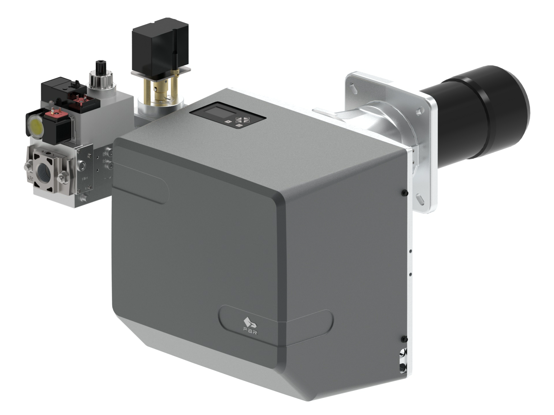
For gas burner modulation—where burner output adjusts proportionally to demand—systems like the FBR BURNER GAS X5/MF TL EL VC LPG require feedback from modulation probes or additional sensor inputs. This burner design operates at a minimum of 69.8 kW and maximum of 349 kW when equipped with optional modulation control, and achieving stable modulation depends critically on proper sensor signal conditioning and proportional valve response.
Step-by-Step Diagnostic Sequence for Burner Control Failures
Step 1: Verify Safety Lockout Status and Manual Reset
Begin by confirming whether the control relay is in active lockout state. Locate the manual reset button (typically red or prominent on the control faceplate). Perform a deliberate reset cycle: press reset, observe if the burner attempts to ignite. If lockout occurs within the proving period (3-5 seconds), proceed to Step 2. If the control does not enter lockout, verify the control is receiving electrical supply and the burner receives fuel pressure at the correct inlet specification (typically 27-33 mbar for natural gas burners in Singapore).
Step 2: Isolate Flame Detection Issues
Flame detection failures represent approximately 60% of unexplained lockouts. Visually inspect the flame sensor for carbon buildup, optical contamination, or mechanical damage. For infrared sensors like the IRD 1010, verify the optical lens has unobstructed line-of-sight to the flame. Clean the sensor window using soft cloth and approved solvents—never use abrasive materials. Test sensor continuity using a digital multimeter set to resistance or continuity mode. Photoresistive cells should show continuity; infrared sensors should exhibit changing resistance values under flame and non-flame conditions. Measure resistance in darkness (typically 5-50 kΩ) and under bright light or flame radiation (typically <1 kΩ). If resistance values are inverted or absent, the sensor requires replacement.
Step 3: Validate Fuel Pressure and Solenoid Function
Using a calibrated pressure gauge connected to the fuel train inlet, measure static fuel pressure with the burner off and dynamic pressure during an ignition attempt. Natural gas systems should maintain 27-33 mbar minimum; oil burners typically require 8-10 bar. Pressure readings below specification indicate supply-side problems (regulator malfunction, supply line obstruction). If pressure is adequate but the solenoid valve does not energize during the ignition sequence, measure voltage across the solenoid terminals using a digital multimeter during an ignition attempt. Solenoids typically require 24V AC or 230V AC (depending on design). No voltage indicates a control relay output failure; voltage without solenoid actuation indicates a failed solenoid requiring replacement.
Step 4: Verify Air Pressure and Fan Operation (Forced-Draft Systems)
For forced-draft burners, measure static air pressure using a manometer connected to the air pressure proving switch. This pressure typically ranges from 5-15 mbar depending on burner design. The control should only attempt ignition when air pressure exceeds the minimum threshold (usually 3-5 mbar). If air pressure is below specification, inspect the fan motor for proper rotation, measure voltage and amperage at the motor terminals, and verify the air intake and combustion head are clear of obstruction.
Step 5: Test Control Relay Logic Sequence
Most control relays provide test terminals or LED indicators showing the control sequence progress. Consult the specific control datasheet (available for the LAL 2.14, SM 592.2, and similar models) to identify test points. Using a digital multimeter set to AC voltage mode, verify voltage presence at each test terminal in sequence: pilot transformer energization, solenoid valve command, and flame detection input. Compare observed sequence against the control's published timing diagram. If the sequence does not progress normally, the relay may require replacement.
Selection Criteria and Best Practices for Control System Maintenance
Preventive maintenance reduces diagnostic complexity significantly. Establish quarterly inspection schedules for flame sensors and fuel strainers. For installations in corrosive or humid environments typical of Singapore's tropical climate, consider upgrading to sealed connector systems and corrosion-resistant sensor materials.
When replacing failed components, always consult the original system documentation to confirm replacement compatibility. Control relay families like the CBM series include multiple variants (CM391, SM 592, LAL 2.14, GE 236, etc.), and incorrect substitution can compromise safety interlocking or cause incompatibility with existing fuel valves and sensors.
For systems utilizing modulation control (such as installations with the FBR BURNER GAS X5), retain documentation of original commissioning data: baseline fuel pressure, modulation signal voltage ranges, and proving period timing. Deviations from these baselines during troubleshooting indicate sensor drift or proportional valve degradation requiring component replacement.
Document all diagnostic findings and corrective actions in a maintenance log. This creates a historical record that helps identify recurring failure patterns (e.g., seasonal flame detection issues suggesting moisture ingress) and informs future maintenance strategies.
Contextual Considerations for Singapore Industrial Environments
Industrial burner installations across Singapore operate in challenging tropical conditions: high humidity, salt-laden air in coastal regions, and rapid temperature variations. These factors accelerate corrosion of electrical connectors and degrade sensor optical elements faster than in temperate climates. When troubleshooting persistent or recurring failures, factor in environmental degradation as a contributing cause and consider upgrading to enhanced protection specifications (IP54 or higher) during component replacement.
Access to technical support and replacement components is excellent in Singapore, with distributors maintaining stocks of standard control relays and sensors. However, diagnostic capability remains critical because expedited component replacement without root cause analysis often results in repeat failures within weeks.
Closing: Professional Support for Complex Diagnostics
Systematic troubleshooting resolves the majority of burner control failures using field-accessible diagnostics and standard tools. However, complex intermittent faults, multiple simultaneous failures, or suspected control relay logic problems warrant professional commissioning support. The diagnostic procedures outlined here establish a foundation for methodical problem isolation and enable productive dialogue with equipment specialists when advanced diagnostics are required.
If your diagnostic efforts do not resolve the fault condition, or if you require verification of specific control relay specifications for your installation, contact 3G Electric's technical team in Singapore. We maintain comprehensive documentation for all burner control families, provide diagnostic support for troubleshooting sessions, and stock replacement components for rapid system restoration. Reach out today to discuss your specific control system challenge and access our technical expertise.