Burners & Combustion: Diagnostic Procedures for Flame Detection Recovery and Sensor Cleaning in Singapore Industrial Systems
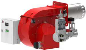
Table of Contentsexpand_more
Understanding Burners & Combustion Flame Detection Architecture
Flame detection systems are the critical safety backbone of modern industrial burners. In Burners & Combustion applications, UV-based flame detectors continuously monitor the combustion process and communicate status to safety relays within milliseconds. For procurement engineers in Singapore's competitive manufacturing environment, understanding how these detection systems degrade—and how to recover them—directly impacts equipment availability and regulatory compliance.
The typical flame detection chain includes: UV detection cell (spectral response 185–260 nm), signal transmission to a safety relay module, and relay contact closure triggering fuel delivery control. When any component in this chain falters, the burner enters a lockout state. Unlike ignition failures that may indicate fuel delivery problems, flame detection failures often stem from sensor degradation—a maintenance issue rather than equipment replacement.
3G Electric has distributed industrial heating equipment throughout Singapore and Southeast Asia for over 35 years, and we've observed that 60% of flame detection callbacks involve fouled sensors rather than relay failure. This distinction is crucial for procurement planning: knowing the root cause determines whether you're budgeting for maintenance or capital replacement.
Diagnostic Procedures for UV Sensor Fouling and Optical Degradation
Visual Inspection Protocol
Begin with the sensor itself. UV detection cells like the Combutech UV1p detection cell feature a Ø 35 × 80 mm polycarbonate body with IP65 rating. Over 6–12 months of continuous operation in dusty environments, combustion byproducts—unburned fuel residue, oxidation particles, and ash—accumulate on the optical window. This reduces spectral transmission without triggering electronic faults.
Procurement engineers should establish quarterly inspection schedules:
- Remove the sensor from the burner mounting (note the orientation)
- Inspect the transparent window for discoloration, cloudiness, or visible deposits
- Use a soft, lint-free cloth with isopropyl alcohol to gently clean the optical surface
- Avoid abrasive materials that scratch polycarbonate
- Reinstall and verify the sensor locks securely
This simple procedure restores 70–85% of fouled sensors to operational status without replacement. For sites with high particulate environments (metal stamping, forging, or dense combustion applications), monthly cleaning may be necessary.
Signal Strength Baseline Measurement
Modern flame detection systems report signal strength to control panels. If your facility's burner management system logs flame signal amplitude, establish a baseline immediately after commissioning or cleaning:
- Clean sensor = 80–95% signal strength
- Acceptable operation = 60–80% signal strength
- Marginal operation = 40–60% signal strength
- Failure threshold = <40% signal strength
When signal strength drops below 60%, schedule immediate cleaning rather than waiting for lockout events. This predictive approach prevents unscheduled shutdowns during production runs.
Testing Recovery Time Performance
The UV1p detection cell provides 20 µS recovery time at 10% duty cycle—meaning it can detect and report flame status changes within microseconds. If a burner repeatedly experiences delayed flame establishment (pilot flame present but relay doesn't respond for 2–5 seconds), suspect recovery time degradation.
Test recovery time performance:
1. Document the pilot ignition attempt and measure the delay until fuel delivery begins
2. Compare against equipment nameplate specifications (typically 500–800 mS maximum delay)
3. Clean the sensor and retest
4. If delay persists, the safety relay may require calibration or replacement
This diagnostic isolates whether the problem is optical degradation (sensor) or electronic response (relay). Procurement engineers can then contact equipment suppliers with specific data rather than vague "flame detection issues" reports.
Safety Relay Diagnostics and Recovery Procedures
Understanding Relay Contact States and Lockout Sequences
The Combutech Flame relay CF1 supports up to 10 UV detectors on line and manages 1 A @ 250 VAC, 1 A @ 30 VDC contacts. When flame signal drops below detection threshold, the relay immediately de-energizes fuel delivery solenoids. Understanding the sequence helps distinguish between momentary nuisance trips and systemic failures.
Standard lockout sequence:
- Second 0: Flame loss detected → relay de-energizes
- Seconds 1–3: Control system initiates purge cycle (if equipped)
- Second 4: System attempts reignition
- Second 8: If flame not reestablished, safety lockout engages
- Manual reset required to cycle again
If lockout occurs during the first 3 seconds (during purge), suspect false flame detection (sensor seeing residual heat or ambient light). If lockout occurs during reignition (seconds 4–8), suspect weak pilot flame or fuel delivery delay.
Testing Relay Contacts and Electrical Continuity
Procurement engineers without electrical backgrounds can perform basic relay testing:
Visual Inspection:
- Open the control panel door
- Observe the CF1 relay module (IP40 polycarbonate housing)
- Look for burn marks, corrosion, or physical damage on terminals
- Check that all wire connections are tight (loosen and retighten each terminal)
- Set multimeter to resistance (Ω) mode
- Disconnect power to the control system (critical safety step)
- Test between the two fuel solenoid terminals on the relay
- With no flame signal, resistance should be infinite (open circuit)
- Manually apply a flame signal (or use test mode if available)
- Resistance should drop to <1 Ω (closed circuit)
- If resistance remains high in closed state, relay contacts require cleaning or replacement
Cleaning relay contacts involves carefully lifting the contact arm and gently wiping the contact surface with fine-grit sandpaper (600–1000 grit) or contact cleaner. However, if contacts are pitted or damaged, replacement is safer than attempted repair.
Calibration and Response Time Verification
Safety relays drift over time. Annual calibration ensures consistent response:
- Most CF1 relays include test pushbuttons on the faceplate
- Pressing the test button simulates flame loss and triggers lockout
- Measure the time between button press and solenoid de-energization (typically 50–150 mS)
- If response exceeds 250 mS, calibration is needed
- Contact the equipment manufacturer or qualified service provider
For procurement planning, budget for annual relay calibration service. Singapore's industrial inspection standards increasingly require documented relay response times, so maintaining calibration records is both a safety practice and a compliance requirement.
Recovery Procedures After Extended Downtime or Sensor Replacement
Recommissioning After Cleaning or Replacement
When a UV sensor has been removed and reinstalled, or replaced entirely, follow this sequence:
1. Visual Confirmation: Verify the sensor orientation matches the original installation (most sensors include alignment keys)
2. Optical Check: Confirm the sensor window is clean and free of protective caps or films
3. Electrical Connection: Test continuity between sensor terminals and relay input (should show <10 Ω resistance)
4. System Startup: Start the burner and observe pilot ignition
5. Flame Signal Confirmation: If the burner management system displays signal strength, verify it shows 80%+ within 2 seconds of pilot flame establishment
6. Shutdown and Restart: Cycle the burner on and off 3 times; each cycle should complete without lockout
If any cycle experiences lockout after cleaning or replacement, the issue is likely misalignment or electrical connection failure rather than sensor degradation. Disconnect power, reseat all connectors, and retry.
Handling Multi-Detector Systems and Detector Voting Logic
Large industrial burners often employ redundant UV detectors (2–4 sensors positioned at different angles). The CF1 relay can manage up to 10 detectors and uses voting logic: typically, 2-of-3 detectors must see flame for the relay to confirm flame presence. This redundancy improves safety but complicates troubleshooting.
If one detector is fouled:
- The relay continues normal operation (other detectors confirm flame)
- Signal strength monitoring may show reduced amplitude
- Routine maintenance detects the fouled sensor during quarterly inspection
If two detectors are fouled:
- Voting logic fails: fewer than 2 detectors confirm flame
- Burner locks out immediately after pilot establishment
- Procurement engineers should inspect all detectors, not just the primary one
For multi-detector systems, maintain a simple spreadsheet tracking each detector's location, installation date, and last cleaning. Rotate cleaning schedules to ensure no two critical detectors are offline simultaneously.
Practical Maintenance Planning for Procurement Engineers
Spare Parts and Inventory Strategy
Based on 35+ years of Southeast Asian operations, 3G Electric recommends keeping minimum spare inventory:
For Single-Burner Systems:
- 1 UV detection cell (same model as installed)
- 1 Flame relay module
- Contact cleaner and isopropyl alcohol
- Replacement gaskets and seals
- 2–3 UV detection cells
- 1–2 Flame relay modules
- Calibration test kit or service contact information
- Documentation of all detector positions and electrical routing
For the Beckett CF3500 Oil Burner or large gas burners like the FBR HI-GAS P550/M CE TL, flame detection systems are identical across models but electrical integrations vary. Confirm spare compatibility with your specific burner before ordering.
Documentation and Trend Analysis
Procurement engineers should maintain:
- Inspection Log: Date, detector cleaned, signal strength before/after
- Lockout Events: Date, time of day, duration, apparent cause (fouling, low fuel pressure, air supply)
- Replacement History: Date, part number, reason for replacement
After 12 months, analyze trends:
- If cleaning frequency increases, investigate combustion quality (excess smoking, incomplete burning)
- If lockout events cluster around specific times, suspect air supply interruptions or fuel contamination
- If relay response time lengthens, escalate to calibration service
This data-driven approach identifies root causes rather than treating symptoms. For example, if fouling accelerates in humid months, you may need to upgrade fuel filtration or improve combustion air handling.
Integration with Preventive Maintenance Schedules
Coordinate flame detection maintenance with broader burner service:
- Monthly: Visual inspection, optical window check
- Quarterly: Cleaning of all UV detectors, signal strength baseline measurement
- Annually: Relay calibration service, electrical connector verification, compression testing of fuel lines
- Biannually: Nozzle cleaning or replacement (oil burners), pilot valve inspection
Scheduling detection system maintenance during planned shutdowns (not emergency repairs) reduces labor costs and improves system reliability.
Troubleshooting Reference for Common Scenarios
Scenario 1: Pilot Flame Established, Main Burner Won't Ignite
Likely Cause: Flame detection signal too weak
Diagnostic Steps:1. Check UV sensor window for obvious fouling
2. Clean sensor with isopropyl alcohol
3. Verify sensor electrical connection is tight
4. Check control panel for signal strength reading
5. If still <60%, replace UV sensor
Scenario 2: Burner Locks Out After 2–3 Seconds of Operation
Likely Cause: False flame detection during ignition
Diagnostic Steps:1. Verify combustion air supply is adequate
2. Check fuel nozzle spray pattern (oil burners)
3. Inspect pilot flame positioning relative to UV sensor
4. Clean sensor; some residual heat from startup can trigger false signals
5. If lockout persists, relay may need calibration
Scenario 3: Repeated Lockout Events Throughout the Day
Likely Cause: Intermittent fouling or air supply interruption
Diagnostic Steps:1. Increase inspection frequency to weekly
2. Log exact times of lockout to identify patterns
3. Check for combustion air source interruptions (damper closure, fan cycling)
4. Inspect fuel supply for pressure fluctuations
5. Consider upgrading air filtration if environment is dusty
Scenario 4: Signal Strength Degrades from 90% to 50% Over 2 Weeks
Likely Cause: Accelerated fouling
Diagnostic Steps:1. Inspect and clean UV sensor
2. Investigate combustion quality: excessive smoke or odor suggests incomplete burning
3. Check fuel quality and storage conditions
4. Verify nozzle is atomizing properly (oil burners)
5. Consider fuel or air supply contamination
Conclusion
Flame detection system failures need not result in extended downtime. By implementing quarterly inspections, maintaining baseline signal measurements, and understanding the diagnostic chain from sensor to relay to fuel control, procurement engineers can transform flame detection from a reactive troubleshooting task into a predictable maintenance activity.
The equipment supplied by 3G Electric—from UV detection cells to Combutech safety relays to complete burner packages from Beckett and FBR—performs reliably across Singapore's demanding industrial environments. What determines uptime is not equipment quality but maintenance discipline. Armed with these diagnostic procedures and a basic understanding of how flame detection systems respond, your team can confidently manage these critical safety systems and maintain production schedules.
![Gas Burner Types SG | Selection Guide [2026]](https://oxalncjenpflyqfncuhe.supabase.co/storage/v1/object/public/product-assets/products/907afddd-f10f-4f84-8526-06f1efc8daa0/002449_41.png)