How to Maintain and Replace Gas Valve Components in Industrial Applications Globally
Gas valve maintenance is one of the most critical responsibilities for maintenance teams and service engineers operating industrial equipment globally. While previous guides have focused on system installation and commissioning, the reality of long-term equipment operation demands a deeper understanding of component wear patterns, preventive maintenance schedules, and safe replacement procedures. This article addresses the practical, day-to-day challenges of keeping gas valve systems operational through systematic component inspection, condition assessment, and timely replacement—ensuring safety, reliability, and cost-effectiveness across diverse industrial environments.
Understanding Gas Valve Component Degradation and Lifecycle Management
Gas valve systems consist of multiple interconnected components, each with its own service life and failure modes. Understanding how these components degrade is fundamental to effective maintenance planning. Thermocouples, for example, gradually lose their thermoelectric output over time due to oxidation and mechanical stress, leading to loss of flame supervision capability. Pressure regulators experience wear in their diaphragms and seats from constant gas flow and pressure cycling. Solenoid valves develop stiction (friction-induced sticking) in their cores due to carbon deposits and corrosion. Pilot lights suffer flame instability from electrode erosion and contamination of the burner orifices.
The rate of degradation varies significantly based on operating environment. High-humidity tropical climates accelerate corrosion of metal components and promote mold growth on electrical connectors. Installations with unfiltered gas supplies experience accelerated wear in regulators and valve seats. Temperature cycling in outdoor or poorly insulated equipment stresses seals and diaphragms. High vibration environments cause mechanical wear in threaded connections and fasteners. Unlike catastrophic failures that announce themselves with system shutdown, component degradation is gradual and often masked by system redundancy or operator workarounds, making regular inspection protocols essential.
Effective lifecycle management requires establishing baseline performance data shortly after installation, then tracking performance metrics over time. This might include monitoring flame stability, pressure output consistency, ignition response time, and gas flow rates. Deviations from baseline indicate advancing degradation and trigger replacement before complete failure. Organizations that implement condition-based replacement strategies reduce unplanned downtime, extend overall system life, and maintain consistent equipment performance across operating conditions.
Critical Gas Valve Components and Their Maintenance Requirements
The foundation of effective maintenance is understanding the specific characteristics and failure modes of each component type. Thermocouples such as the CBM Thermocouple Sit INT.600 are temperature sensors that generate the millivoltage signal needed to hold solenoid valves open during normal operation. They typically degrade from oxidation of their measuring junction, leading to reduced output voltage and eventual flame supervision failure. Inspection involves measuring actual thermocouple output against manufacturer specifications—typically 10-25 millivolts depending on flame temperature. Replacement is straightforward but requires careful handling to avoid bending the thermocouple stem and ensuring proper seating in the pilot light assembly.
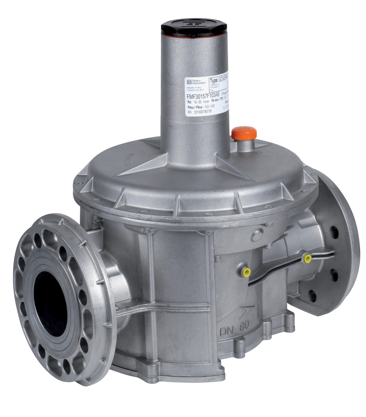
Pressure regulators such as the CBM Pressure Regulator with DN50 flanges maintain consistent gas pressure regardless of inlet pressure variations or flow rate changes. The internal diaphragm gradually loses elasticity from continuous flexing and exposure to gas components. Regulators may develop internal leakage (gas flowing past the seat) or become stuck in the open or closed position. Inspection involves checking outlet pressure stability under varying load conditions and listening for internal whistling sounds indicating seat wear. DN65 models are available for larger capacity applications. Replacement requires proper depressurization and careful removal of flanged connections to avoid cross-threading.
Solenoid valves such as the CBM Solenoid Valve BC in stainless steel operate through electromagnetic actuation of an internal plunger that opens or closes the main gas port. They accumulate carbon deposits and corrosion products on the plunger stem, causing sluggish response, partial opening, or complete sticking. Inspection involves testing the solenoid coil resistance with a multimeter (should typically read 100-300 ohms depending on model) and listening for audible clicking when energized. The Filter Cartridge 10604/5/6 protects these components by removing particulates from the gas supply, so regular filter element replacement extends solenoid valve life significantly.
Pilot light burners such as the CBM 2-Flame Pilot Light require inspection of flame characteristics: the flame should be stable, centered on the thermocouple tip, and display a blue primary flame with minimal yellow tips. Instability or misalignment indicates electrode erosion, orifice blockage, or air shutter misalignment. These components are relatively inexpensive but require careful electrode and orifice cleaning before replacement. Universal 2-flame models with 3-position flexibility provide versatility for diverse equipment types while maintaining consistent maintenance requirements.
Step-by-Step Gas Valve Component Replacement Procedure
Step 1: Preparation and Safety Verification
Shut down the equipment and allow all components to cool to ambient temperature. Close isolation ball valves on both sides of the gas valve assembly if present. If isolation valves are not available, close the main fuel supply and open the vent valve to depressurize the system. Verify zero gas pressure using a pressure gauge. Never assume a system is depressurized—always verify with instrumentation. Document the current system configuration by photographing valve orientation, electrical connections, and gas line routing before any disconnection.
Step 2: Component Identification and Removal
Locate the specific component requiring replacement using equipment documentation. For thermocouples, note the connection type (compression fitting vs. threaded vs. welded). Using appropriately sized wrenches, hold the fitting body stationary with one wrench while turning the nut with another to prevent twisting the thermocouple tube. For solenoid valves, disconnect the electrical connector by firmly pulling on the connector body (not the wire). Loosen and remove the valve using the hex nut at the base, supporting the valve body to prevent stress on the connected gas lines. For pilot light burners, typically only a compression nut and electrical spade connector require disconnection.
Step 3: Inspection of Ports and Connections
Once the component is removed, inspect the connection port for debris, corrosion, or damaged threads. Use a soft brush to remove any loose particles, but never introduce cleaning liquids into gas ports as residue can damage replacement components. For compression fittings, examine the ferrule for cracks or permanent deformation—replace if damaged to ensure proper sealing on the new component.
Step 4: Installation of Replacement Component
Apply a thin layer of thread seal tape to threaded connections (typically 2-3 wraps). For compression fittings, ensure both ferrule and seat are clean. Insert the new component hand-tight first, then use wrenches to snug the connection—hand-tight plus one-quarter turn is typical. Do not over-tighten, as this can damage ferrules or strip threads. For electrical connections, firmly insert the connector until you hear or feel a click indicating proper seating.
Step 5: System Pressurization and Leak Testing
Slowly open isolation valves or restore main fuel supply. Using a soap solution on all connections, look for bubbles indicating gas leakage. Test operation of the equipment at normal settings, then again at maximum load. Verify that the replacement component responds appropriately—pressure regulation should be stable, ignition should be reliable, and flame should be stable. Document the replacement in equipment maintenance records with date, component model number, and any observations about system performance.
Selection Criteria and Best Practices for Component Replacement
When selecting replacement components, always reference the original equipment manufacturer's specifications rather than assuming similar-looking components are compatible. Gas valve systems are carefully balanced—pressure regulator settings affect ignition response time, thermocouple output affects flame supervision sensitivity, solenoid valve response time affects combustion efficiency. Using non-specified components can compromise safety and performance.
Establish preventive replacement schedules based on manufacturer recommendations and your operational history. Most thermocouples should be replaced every 3-5 years regardless of apparent condition due to gradual thermoelectric output degradation. Pilot light burners typically require replacement every 2-3 years in continuous-duty applications. Solenoid valves and pressure regulators can operate for 10+ years if proper filtration is maintained, but inspection every 2-3 years is prudent. Keep spare components in inventory for critical systems—the cost of spare thermocouples and solenoid valves is minimal compared to unplanned downtime.
Maintain detailed records of all replacements, including dates, part numbers, and any performance changes observed. These records help identify patterns—for example, if thermocouples consistently fail after 18 months rather than the expected 5 years, this indicates either an underlying pressure or temperature excursion or improper installation technique. Use gas detection equipment to verify safety during maintenance work, especially when working in confined spaces or poorly ventilated areas. Consider implementing a tag-out/lock-out procedure for gas equipment to prevent accidental startup during maintenance.
Specialized Maintenance for Multifunctional Gas Control Systems
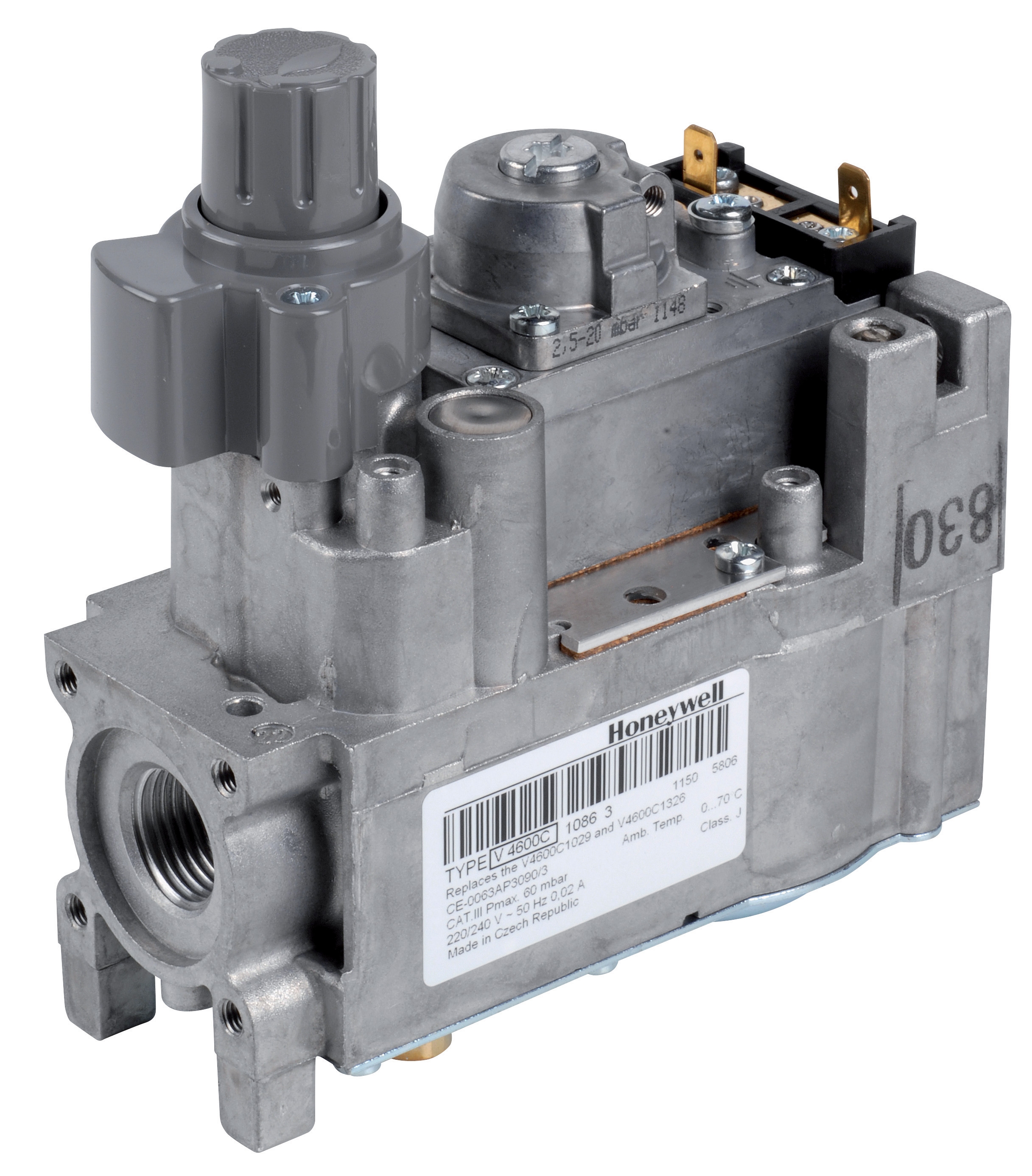
Modern multifunctional gas controls like the CBM Minisit Gas Block 0710750 integrate multiple functions—pressure regulation, temperature control, and flame supervision—into a single compact unit. These systems require different maintenance approaches than traditional separate components. Rather than replacing individual internal components, most manufacturers recommend complete unit replacement when degradation is detected, as internal repairs risk misalignment of precision components. However, external access points for filter cartridges and occasional cleaning of the pilot burner orifice can extend service life significantly.
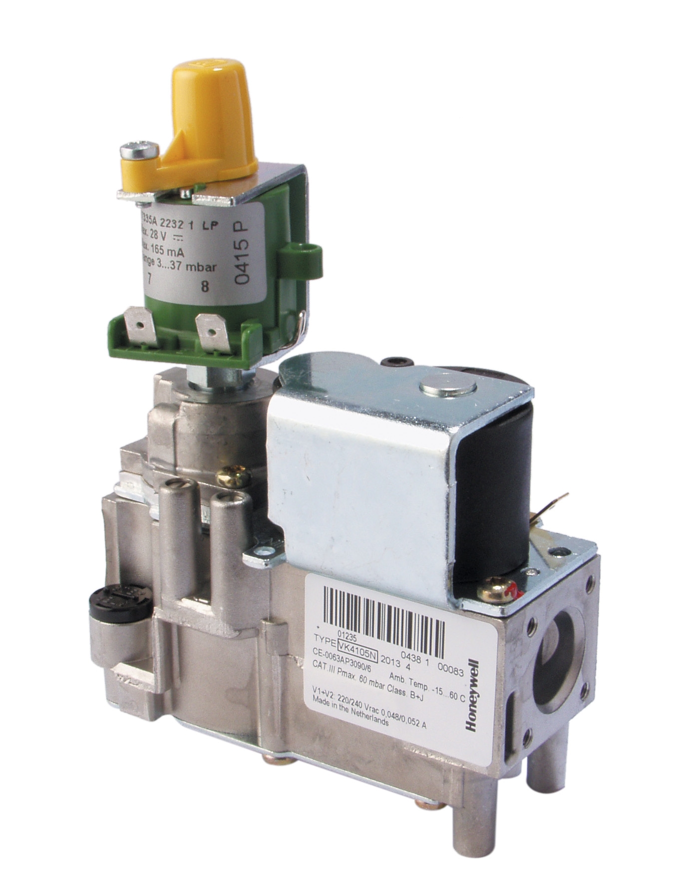
Similarly, advanced gas control units with modulating pressure regulators, such as systems using the CBM Gas Block VK 4105 N 2013 U, contain electronic control circuits that degrade differently than purely mechanical components. These systems benefit from periodic cleaning of air intake vents, verification of electrical connector integrity, and testing of modulation response through software diagnostics when available. Maintenance teams should document baseline performance parameters early in the system's life to provide comparison points for detecting degradation.
For facilities operating multiple equipment units with integrated gas controls, consider implementing a spare unit replacement strategy rather than on-site repair. The cost of maintaining a fully stocked spare control unit is often lower than the labor cost of troubleshooting and component-level repair, and replacement time is measured in hours rather than days.
Gas valve maintenance represents the most cost-effective investment maintenance teams can make in industrial equipment reliability. By understanding component degradation patterns, following systematic inspection protocols, and planning preventive replacements before failure, you extend equipment life, improve safety, and reduce operational costs. Whether you operate equipment in Singapore's tropical climate, cooler northern regions, or any environment in between, these principles apply universally. For technical guidance specific to your equipment, access to detailed component documentation, or supply of replacement components from established manufacturers, contact 3G Electric's team of industrial equipment specialists. We've served maintenance teams globally since 1990 and maintain comprehensive inventory of gas valve components and accessories to support your preventive maintenance programs.