Gas Valves & Regulation: Diagnostic Testing and Performance Verification for Singapore Maintenance Teams
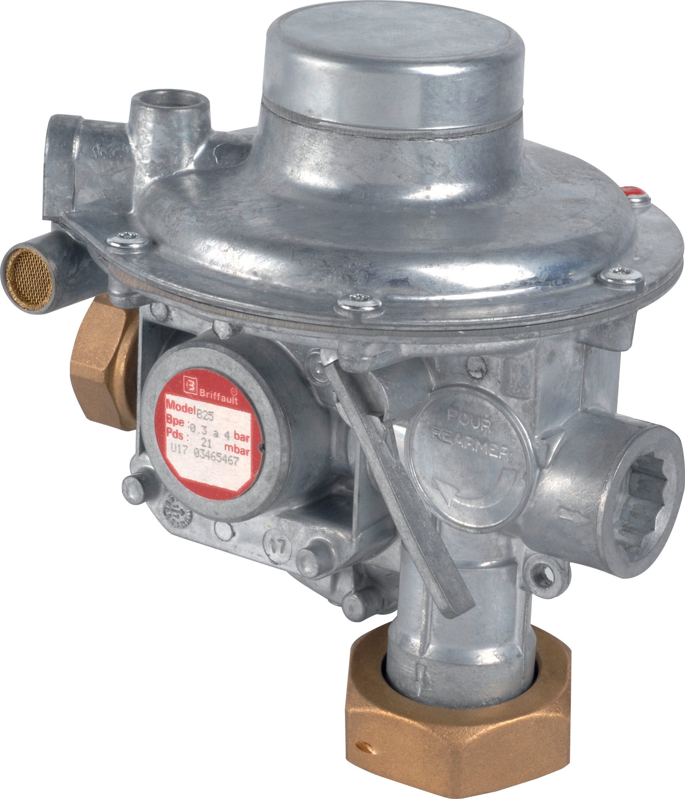
Table of Contentsexpand_more
Introduction: Why Diagnostic Testing Matters for Gas Valve Systems
Gas valves and regulation equipment are critical safety components in Singapore's industrial infrastructure, from petrochemical facilities to food processing plants and commercial heating systems. Unlike routine maintenance, systematic diagnostic testing reveals performance degradation before failures occur—preventing costly downtime, safety incidents, and regulatory violations.
With over 35 years of industrial equipment distribution experience, 3G Electric understands that maintenance teams often lack standardized testing protocols tailored to Singapore's tropical climate and operational demands. This guide bridges that gap by providing actionable diagnostic procedures that help you verify valve performance, identify emerging problems, and document compliance evidence for regulatory audits.
Section 1: Pre-Test System Preparation and Safety Requirements
Safety Lockout Procedures
Before beginning any diagnostic testing on gas valves and regulation systems, implement comprehensive lockout-tagout (LOTO) procedures compliant with Singapore's Ministry of Manpower guidelines. Isolate the gas supply upstream of the test point using isolation ball valves, close manual shutoff valves, and verify isolation by attempting to ignite burners or activate gas outlets. This confirms zero pressure and eliminates ignition risks during testing.
Document all isolation points in your maintenance logbook with timestamps. Use physical lockout hasps rated for your facility's pressure ranges—typically 250 bar for high-pressure systems. Never rely on solenoid valve closure alone; always supplement with manual isolation valves positioned between your test zone and the gas source.
Pressure Relief and Venting
Before disconnecting any components from gas valves and regulation assemblies, vent system pressure safely. Connect a low-pressure relief hose to any isolation cock or test point, directing gas flow to atmosphere or a fume hood. Open the relief slowly—rapid depressurization can damage internal seals and release contaminants into your work area.
Allow the system to remain vented for at least 2 minutes to ensure complete pressure decay. Use a digital pressure gauge to confirm zero pressure at the test point before proceeding. This step prevents sudden gas release during component disconnection and protects your team from pressure-related injuries.
Environmental and Equipment Setup
Gas valves and regulation systems perform differently across temperature ranges. Singapore's ambient temperature typically ranges 24–32°C, but test areas near furnaces or steam lines may exceed 40°C. When testing pressure regulators like the Francel B25/37mb with safety relief, verify ambient temperature and allow equipment to stabilize for 15 minutes before taking baseline measurements.
Arrange your testing workspace to minimize vibration and external pressure variations. Use a stable work surface or bench with a drip tray (polyethylene or steel) to contain any residual gas or trapped condensate. Position your pressure gauge and test equipment horizontally to eliminate elevation-related measurement errors. Keep a fire extinguisher (dry powder, Class B rated) within arm's reach—Singapore building codes require this for all fuel gas testing areas.
Section 2: Functional Diagnostic Testing Procedures
Step 1: Visual Inspection and Baseline Documentation
Begin every diagnostic sequence with a comprehensive visual inspection. Examine the valve body for corrosion, discoloration, or physical damage indicating impact or vibration stress. Check connection threads and fittings for gas leaks using a soapy water solution—bubbles indicate escaping gas requiring immediate repair.
For regulators like the Francel B25/37mb, inspect the vent hole (10 mm size on this model) for blockages caused by dust, corrosion, or sealant debris. A blocked vent prevents pressure relief and causes uncontrolled outlet pressure rise—a critical safety hazard. Clean vent holes with compressed air directed away from your face, never with metal tools that could damage the orifice.
Photograph all components showing serial numbers, manufacturing dates, and pressure ratings. Create a baseline documentation record including valve type, installation date, last service date, and observed operating pressure. This baseline enables you to track performance trends over months or years, identifying gradual degradation patterns.
Step 2: Static Pressure Testing
Static pressure testing verifies that gas valves and regulation systems hold pressure without leakage. This test requires a precision digital pressure gauge (±0.5% accuracy minimum, 0–10 bar range for low-pressure applications, 0–400 bar for high-pressure systems).
Procedure:
- Close all downstream service outlets (burner manual shutoffs, pilot lights, appliance demand valves)
- Connect your test gauge to the outlet test cock on the regulator
- Slowly open the gas supply upstream, allowing pressure to stabilize over 30 seconds
- Record outlet pressure and compare against the regulator's nameplate setting (typically 37 mbar for laboratory systems, 0.5–4 bar for industrial burners)
- Maintain pressure for 10 minutes—pressure should remain stable within ±2% of initial reading
- If pressure rises continuously, internal leak paths exist in the regulator; schedule component replacement
- If pressure drops more than 5%, external leaks exist at connections or the valve body
Document all readings with timestamps. For regulators like the Francel B25/37mb, expected outlet pressure should be 37 mbar ±2 mbar under static conditions with zero gas flow.
Step 3: Flow Testing and Dynamic Regulation
Dynamic testing reveals whether gas valves and regulation systems maintain stable pressure during actual gas consumption—the most critical real-world performance indicator.
Procedure:
- Connect your test gauge to the outlet test point
- Establish zero flow and record "no-flow" outlet pressure (baseline from Step 2)
- Open downstream burner or load to create realistic gas flow (for pilot lights, approximately 0.5 m³/h; for main burners, 5–15 m³/h depending on equipment size)
- Record outlet pressure after 1 minute of continuous flow
- Compare against static pressure—acceptable variance is ±3% for industrial systems
- If pressure drops more than 5% during flow, the regulator cannot supply sufficient gas; check for downstream blockages or undersize the regulator for your actual flow requirement
- If pressure rises during flow (opposite effect), internal diaphragm failure exists; schedule immediate regulator replacement
Maintain flow for at least 5 minutes, recording pressure at 1-minute intervals to identify oscillation patterns. Stable readings indicate proper valve function; rising/falling pressure waves suggest worn internal components or inadequate downstream receiver volume (for high-pressure systems like Pratissoli R1/400 regulating valves).
Step 4: Safety Relief Verification
For gas valves and regulation systems with integrated safety relief (like the Francel B25/37mb model), verify relief function prevents dangerous overpressure conditions.
Procedure:
- Close all downstream isolation valves, creating a trapped volume between the regulator outlet and your closed shutoff
- Slowly increase inlet pressure while monitoring outlet gauge
- Continue increasing pressure until you observe outlet pressure stop rising—this indicates relief activation
- Record the relief activation pressure; compare against the regulator's "cracking pressure" specification (typically 37 mbar + 10–15% tolerance)
- Slowly decrease inlet pressure and observe whether outlet pressure decreases smoothly or sticks at elevated pressure
- If relief fails to activate or activates above specification + 20%, the safety valve requires professional cleaning or replacement
Safety relief testing is critical for Singapore compliance with TN 2.01 (Technical Notes on Gas Standards). Document relief activation pressure as evidence of proper safety function during regulatory audits.
Step 5: Leak Detection at Connection Points
After pressure testing, perform systematic leak detection at all connection points to identify potential gas escape routes.
Procedure:
- With system at operating pressure (following Step 2 static test), prepare soapy water solution (commercial leak detector or 3 parts water + 1 part dish soap)
- Apply solution with soft brush to each connection: inlet fitting, outlet fitting, gauge test ports, vent hole area, and valve body seams
- Observe for bubble formation indicating escaping gas
- Mark any leak locations with tape; record on your diagnostic form
- Small leaks (pinhole size, <0.5 mm bubbles/second) indicate loose fittings requiring wrench tightening or joint sealant renewal
- Large leaks (vigorous bubble streams) indicate damaged seals or cracked valve bodies requiring immediate component replacement
After applying soapy solution, always rinse thoroughly with clean water and dry connections to prevent corrosion in Singapore's humid climate.
Section 3: Specialized Testing for High-Pressure Regulation Systems
For industrial applications using high-pressure regulators like the Pratissoli R1/400 regulating valve (400 bar rated), add these specialized diagnostic tests:
Differential Pressure Testing
High-pressure regulating valves require verification of upstream-to-downstream pressure differential. The Pratissoli R1/400 maintains stable output under variable inlet pressure—critical for pump system stability.
Procedure:
- Connect pressure gauges to both inlet and outlet test cocks
- Establish full pump flow (110 L/min for the R1/400 model)
- Record inlet and outlet pressures simultaneously
- Calculate differential: Inlet pressure – Outlet pressure
- Typical differential for R1/400 systems: 50–100 bar depending on pump load
- If differential exceeds specification, the regulator spool valve has internal wear; contact Pratissoli service
- If differential drops below specification, pressure relief is opening prematurely; adjust relief setting or replace valve
Hysteresis and Stability Testing
Regulating valve response to changing flow loads indicates internal component wear. This test reveals sluggish or over-responsive behavior.
Procedure:
- Establish 50% system flow; record outlet pressure
- Rapidly increase flow to 100%; measure time for pressure to stabilize (should be <2 seconds)
- Record new stabilized pressure (should vary <5% from 50% flow reading)
- Decrease flow back to 50%; measure re-stabilization time
- Repeat cycle 3 times
- Consistent response times and pressure variance indicate healthy valve
- Increasing re-stabilization times or widening pressure variance suggest spool valve stiction; schedule maintenance cleaning
Section 4: Documentation, Calibration Verification, and Compliance Records
Creating Diagnostic Test Reports
Maintain systematic diagnostic records for every gas valve and regulation system tested. Include:
- Equipment identification: Valve model, serial number, location code, installation date
- Test date and technician: Name, initials, date/time of test
- Environmental conditions: Ambient temperature, humidity (critical for Singapore's 85%+ average humidity)
- Baseline readings: Static pressure, outlet pressure, inlet pressure (for high-pressure systems)
- Dynamic readings: Pressure under flow, re-stabilization time, relief activation pressure
- Leak locations: Sketches or photos marking any identified leaks
- Actions taken: Repairs performed, components replaced, adjustments made
- Next service date: Recommend following intervals based on test results
Store all diagnostic records in a central maintenance management system (Excel spreadsheet or dedicated CMMS software). Review trends quarterly to identify patterns requiring component replacement or regulator upsizing.
Pressure Gauge Calibration Verification
Your diagnostic results are only as accurate as your measuring instruments. Every 12 months, send pressure gauges to an ISO/IEC 17025 accredited calibration service (Singapore has several certified labs). Attach calibration certificates to your diagnostic records.
Between calibrations, perform spot-checks using secondary reference gauges. If readings diverge >2% from a recently calibrated gauge, discontinue using the suspect gauge until professional calibration is completed.
Regulatory Compliance Documentation
Singapore's building control authorities (BCA) and Gas Appliance Safety Association (GASA) require documented evidence of gas system testing and maintenance. Your diagnostic records serve as compliance evidence during inspections.
Key documentation requirements:
- Annual pressure regulator testing (TN 2.01 compliance)
- Safety relief function verification (recorded relief activation pressure)
- Leak detection results (soapy water test documentation)
- Technician qualifications and certifications
- Service history and corrective actions taken
Maintain these records for minimum 5 years; many facilities retain 10+ years for liability protection.
Recommended Products from 3G Electric
When diagnostic testing reveals the need for component replacement or system upgrades, 3G Electric supplies industry-standard equipment:
- For laboratory and low-pressure systems: Francel B25/37mb pressure regulator with integrated safety relief provides 37 mbar outlet pressure with dual safety features
- For high-pressure pump systems: Pratissoli R1/400 regulating valve handles 400 bar pressure with 110 L/min flow capacity, ideal for KE, EV, and KT-series pump integration
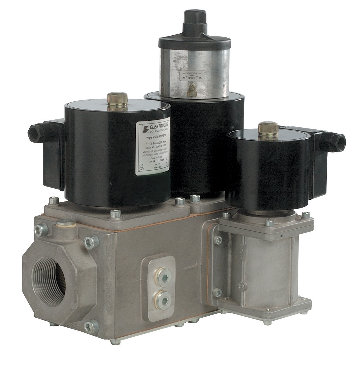
- For pneumatic control applications: Elektrogas VMM 20-25 end-of-stroke contact valve (6 bar rated, EN 161 compliant) provides reliable gas flow control with simple 3 mm Allen wrench adjustment
- For steam system regulation: ELV steam solenoid valve DN 1/2 controls steam flow in heating and process applications, rated 0.5–10 bar with 25 bar maximum differential pressure
With 35+ years of industrial equipment distribution, 3G Electric maintains stocks of these components in Singapore for immediate delivery, supporting your maintenance schedules without extended lead times.