Multi-Component Flow System Troubleshooting Guide: Industry Applications for Global Operations
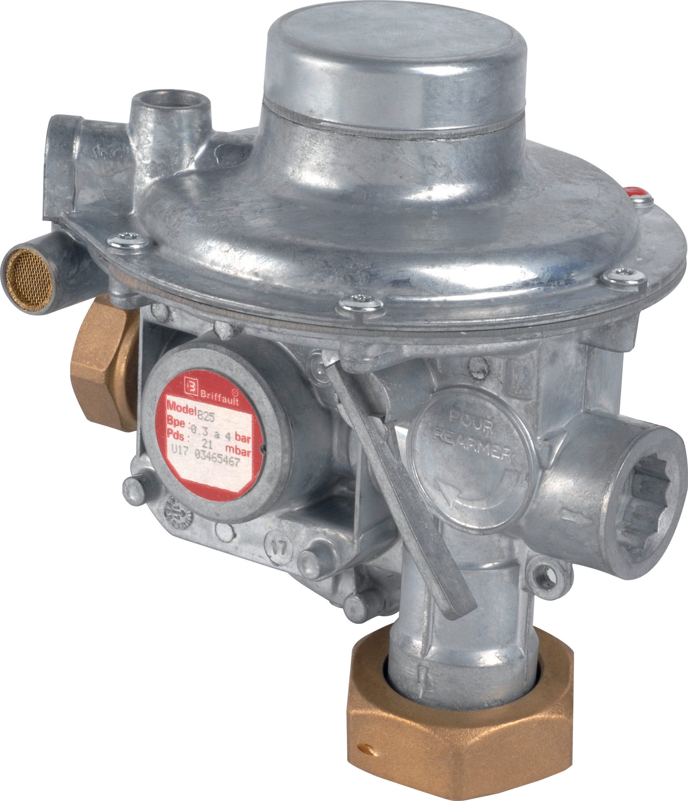
Table of Contentsexpand_more
Understanding Multi-Component Flow System Architecture in Industry Applications
Modern industrial operations rarely depend on single components working in isolation. Flow systems integrate pumps, pressure regulators, nozzles, and distribution lines into complex networks where each element influences overall performance. With 35+ years of experience supplying industrial equipment globally, 3G Electric has observed that the majority of system failures trace back to misdiagnosis at the component level—technicians often replace functioning parts while the actual problem lies in integration, calibration, or selection mismatch.
Industry Applications span cleaning systems, coating operations, fuel delivery, and process automation. Each demands specific flow rates, pressure stability, and spray characteristics. Understanding how these components interact is critical for rapid diagnosis and cost-effective repairs.
Diagnostic Procedures for Pump Flow and Pressure Performance
Step 1: Establish Baseline Operating Parameters
Before troubleshooting, document the system's design specifications:
- Required flow rate (L/min)
- Operating pressure (bar)
- Viscosity and type of fluid
- Ambient temperature conditions
- Duty cycle (continuous vs. intermittent)
Common pump models like Pratissoli KF30 deliver 106 L/min at 200 bar, while the Pratissoli MW40 provides 211 L/min at 210 bar for higher-capacity applications. For compact systems, the Interpump E1D1808 L offers 8 L/min at 180 bar—ideal for portable or space-constrained installations.
Step 2: Measure Actual vs. Expected Output
Install inline pressure gauges and flow meters at strategic points:
- Pump discharge (primary pressure reading)
- Regulator inlet and outlet
- Final nozzle or application point
Flow deficiencies typically indicate:
- Cavitation: Occurs when inlet pressure drops below fluid vapor pressure. Check suction line for restrictions, verify fluid level in reservoirs, inspect inlet filters for blockage.
- Worn pump internals: Gear teeth or displacement components deteriorate over time. Flow loss of 10-15% may be acceptable; exceeding 20% suggests replacement.
- Incorrect rotational speed: Verify motor RPM matches pump design. A 5% speed reduction produces approximately 5% flow reduction.
Pressure anomalies signal different root causes:
- Pressure below specification: Low inlet pressure, worn pump, partially closed discharge valve, or clogged filters.
- Pressure spikes or oscillation: Relief valve chattering, water hammer in lines, or undersized accumulator (if equipped).
- Pressure higher than set point: Regulator malfunction, blockage downstream, or oversized pump for actual system demand.
When integrating a Francel B25/37mb pressure regulator, verify the 37 mbar outlet setting matches system requirements. If system demands exceed regulator capacity, upstream pressure will remain uncontrolled.
Nozzle and Spray Pattern Diagnostics
Identifying Spray Pattern Degradation
Industry Applications in coating and cleaning rely on consistent spray geometry. The Euspray flat jet nozzle HP 1/4"M BSPT delivers a 25° spray angle—deviation from this pattern indicates:
1. Partial blockage: Inspect the nozzle orifice for mineral deposits, debris, or crystallized residue. Soak in appropriate solvent (water for water-based fluids, specialized cleaners for oils).
2. Internal erosion: Extended high-pressure operation (above 200 bar for standard nozzles) causes internal surfaces to wear, widening the spray angle and reducing impact force.
3. Thread or sealing damage: Cross-threaded installation or over-tightening damages the 1/4" BSPT connection, causing leakage and pressure loss.
4. Flow rate mismatch: Verify the nozzle size index (30 in this example) matches the pump's discharge capacity. Oversized nozzles create weak spray; undersized nozzles generate excessive backpressure.
Practical Nozzle Testing Procedure
Without removing the nozzle:
- Observe spray pattern from multiple angles at operating pressure
- Compare against manufacturer documentation or known-good reference
- Measure spray distance and width consistency
- Check for uneven distribution or asymmetrical spreading
If defects are confirmed, remove and inspect internally. Most spray issues resolve with thorough cleaning; replacement is necessary only if erosion or damage is visible.
System Integration and Component Compatibility Challenges
Pressure Regulator Placement and Function
Pressure regulators don't reduce flow—they maintain pressure setpoints by relieving excess flow back to tank. Placement errors cause:
- Upstream regulation: Installing a regulator immediately after the pump wastes energy and generates heat as excess fluid bypasses back to tank.
- Downstream regulation: Placing regulators too far from the application point allows pressure fluctuations in connecting lines to affect actual working pressure.
Best practice: Locate the Francel B25/37mb as close as practical to the application, with short rigid piping to minimize pressure lag and oscillation.
Pump Selection for Actual System Demand
Over-specifying pump capacity creates efficiency losses:
- A Pratissoli MW40 (211 L/min) running at only 50 L/min requirement means 75% of output bypasses through relief, generating 160°C+ heat and reducing component life.
- Undersized pumps (e.g., Interpump E1D1808 L at 8 L/min for a 50 L/min application) cannot meet demand, causing system starvation and nozzle pressure loss.
Match pump displacement to actual average flow demand with 20-30% reserve capacity for transient peak loads.
Fluid Compatibility and Viscosity Management
Industry Applications use varied fluids: water for cleaning, mineral oil for hydraulics, synthetic blends for high-temperature processes. Viscosity affects all components:
- Pumps rated for ISO VG 46 mineral oil lose 15-30% output when operated with thicker fluid
- Regulators designed for low-viscosity fluids show sluggish response with heavy oil
- Nozzles may clog if fluid contains sediment or incompatible additives
Always verify regulator, pump, and nozzle fluid compatibility specifications before system startup.
Common Failure Patterns and Resolution Strategies
Pattern 1: Sudden Pressure Loss During Operation
Diagnosis: System holds pressure at startup, then loses 20-50 bar within minutes.
Root causes:
- Internal pump seal failure (fluid appears in motor coupling)
- Regulator internal bypass damage (test by plugging regulator outlet—if pressure stabilizes, regulator is faulty)
- Cracked hose or fitting (visual inspection and pressure test with soapy water reveal leaks)
Pattern 2: Flow Adequate but Nozzle Impact Weak
Diagnosis: Spray distance and pattern appear correct, but application effectiveness drops (coating coverage poor, cleaning slower).
Root causes:
- Pressure below specification (regulator setpoint drifted)
- Nozzle tip erosion reducing orifice precision
- Incorrect nozzle size for the pump (mismatch between Euspray nozzle index and pump capacity)
Pattern 3: System Shuts Down Intermittently Without Manual Reset
Diagnosis: Pump runs for 5-30 minutes, then stops; power cycling restarts it briefly.
Root causes:
- Thermal overload from excessive relief bypass (oversized pump, undersized nozzle)
- Cavitation at pump inlet from low fluid level or restricted suction line
- Pressure switch malfunction triggering shutdown
Maintenance Intervals for Industry Applications
Based on 35+ years of field experience, 3G Electric recommends:
- Weekly: Visual inspection for leaks, fluid level check, pressure gauge reading documentation
- Monthly: Nozzle cleaning and spray pattern verification; regulator outlet pressure confirmation
- Quarterly: Complete system pressure profile measurement across all components; fluid sampling for contamination
- Annually: Pump flow test at operating temperature; regulator internal inspection and calibration; replacement of all wear seals if system has exceeded 2000 operating hours
Proactive monitoring prevents unplanned downtime across global Industry Applications from manufacturing floors in Asia to processing plants in Europe and North America.
Conclusion
Multi-component flow systems demand systematic diagnostic approach. Start with documented baseline specifications, measure actual performance at multiple points, isolate failures to individual components, and verify compatibility after repairs. Products like the Pratissoli KF30 pump, Francel B25/37mb regulator, and Euspray nozzle are engineered for reliability, but their performance depends on correct integration and maintenance. When problems arise, methodical troubleshooting—rather than component replacement guesswork—restores efficiency and extends equipment life across all Industry Applications.