Thermoelectric Flame Supervision in Gas Burner Controls & Safety Systems: A Maintenance Engineer's Guide
Thermoelectric Flame Supervision in Gas Burner Controls & Safety Systems: A Maintenance Engineer's Guide
Thermoelectric flame supervision represents one of the most reliable and cost-effective methods for monitoring flame presence in atmospheric and fan-assisted gas burners worldwide. Unlike electronic flame detection sensors that rely on optical properties, thermoelectric supervision devices generate electrical signals directly from heat—making them inherently robust in environments where combustion conditions fluctuate or where optical surfaces become fouled. For maintenance teams and service engineers managing industrial burner installations, understanding how thermoelectric supervision integrates with gas burner control systems is essential to diagnosing failures, optimizing performance, and ensuring regulatory compliance across global industrial applications.
Understanding Thermoelectric Flame Supervision: Core Principles and System Integration
Thermoelectric flame supervision operates on a straightforward principle: a thermocouple positioned in the flame generates a small electrical voltage (typically 20–30 millivolts) proportional to the flame temperature. This voltage is continuously monitored by a control relay or safety module, which interprets the signal to confirm flame presence. When voltage drops below a preset threshold—indicating flame loss or ignition failure—the control system immediately triggers a lockout sequence, shutting off gas supply to prevent dangerous unburned fuel accumulation.
What makes thermoelectric supervision particularly valuable in global industrial settings is its passive operation: it requires no external power source to generate the flame-detection signal. A thermocouple works through the Seebeck effect alone, creating voltage whenever temperature differential exists between its hot and cold junctions. This inherent reliability makes thermoelectric devices ideal for environments where power supply stability is uncertain or where redundant safety layers are mandatory by regulation.
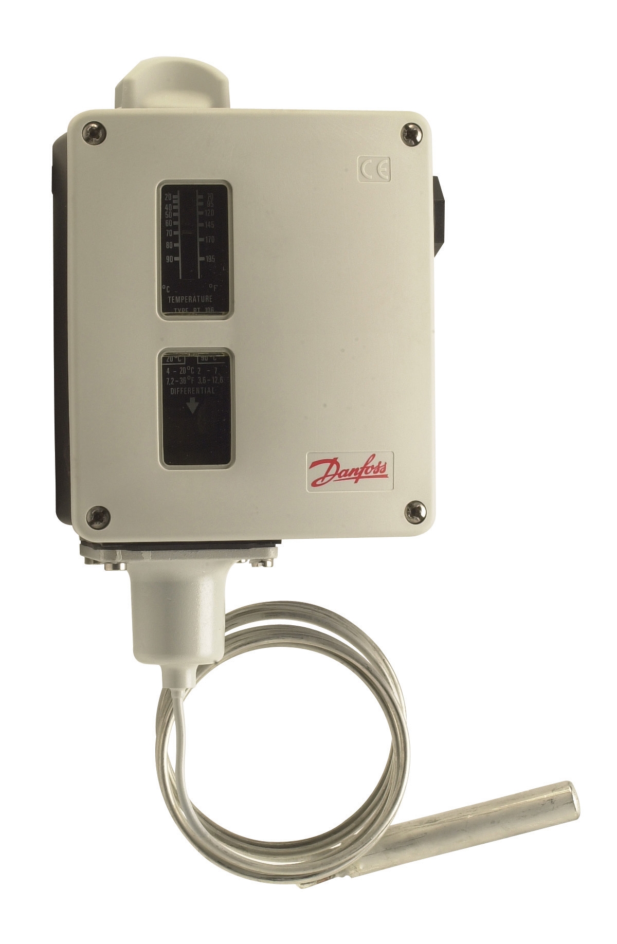
System integration typically involves three functional layers: (1) the thermocouple itself, positioned strategically in the pilot or main flame; (2) a safety control module that processes the thermocouple output and enforces lockout logic; and (3) the main burner control relay that coordinates ignition timing, gas valve sequencing, and post-purge cycles. The thermocouple signal feeds into the control module's input stage, where it is compared against a calibrated reference voltage. If the flame signal remains valid throughout the ignition sequence and during normal operation, the system permits the burner to continue firing. Loss of signal at any critical point triggers an immediate shutdown.
Maintenance teams must recognize that thermoelectric supervision is not instantaneous: there is a measurable delay between flame loss and control module response, typically 2–4 seconds depending on thermocouple thermal lag and module software logic. This response window is designed into safety standards such as EN 126 (Multifunctional devices for gas burning appliances), ensuring that flame supervision operates within predictable, testable parameters.
Technical Product Integration: Thermocouples and Multifunctional Gas Blocks
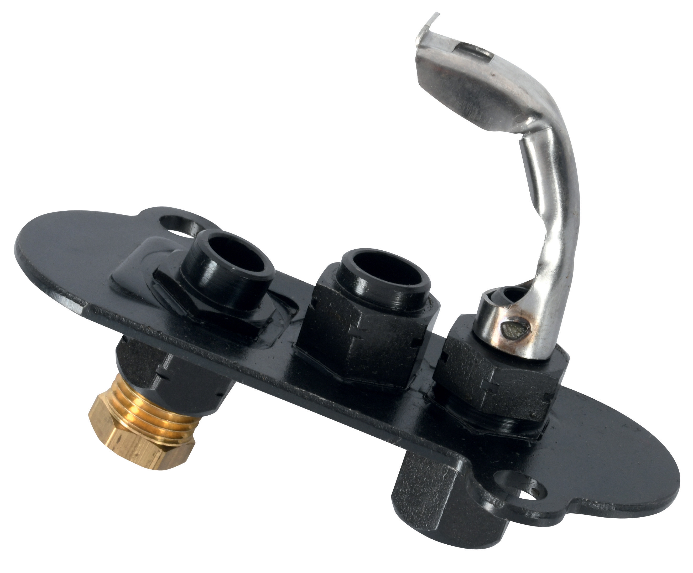
The CBM Thermocouple Sit INT.600 exemplifies thermoelectric supervision components used in industrial gas burner installations. This 9×1 mm thermocouple is designed to withstand sustained flame temperatures while maintaining electrical isolation and mechanical durability. The INT.600 integrates with multifunctional gas blocks such as the CBM Minisit 710, which combines pressure regulation, temperature control, and flame supervision logic into a single compact module.
The Minisit 710 represents a modern approach to thermoelectric flame supervision integration. Rather than requiring separate control relays and external wiring, the Minisit consolidates multiple safety functions into one device: it accepts the thermocouple signal, processes flame supervision, manages pressure regulation (typically 5–25 mbar for atmospheric burners), and provides thermostatic temperature control for appliances such as boilers, catering equipment, and room heaters. This integration reduces wiring complexity, minimizes potential failure points, and simplifies commissioning for maintenance teams working in the field.
For burners requiring dedicated safety control architecture, gas control relays such as the CBM Relay SM 592.2 TW1.5/TS10 or CBM CM391.2 relay series accept thermocouple signals and enforce rigid lockout logic. These relays are part of the EUROBOX and EUROGAS control families, specifically engineered for atmospheric and fan-assisted burners operating intermittently (non-permanent operation). The thermocouple connection is typically a standard M14×1 or similar threaded port on the control module's terminal block.
When commissioning or troubleshooting thermoelectric supervision, maintenance engineers should verify several critical parameters: (1) thermocouple output voltage under stable flame conditions (should be 15–30 mV minimum); (2) response time to flame loss (control module should shut down gas supply within 4 seconds); (3) mechanical security of the thermocouple installation (vibration or thermal expansion can cause disconnection); and (4) cleanliness of electrical contacts at the thermocouple terminals and control module input stage. Oxidized or corroded contacts are a common cause of intermittent flame supervision failures, particularly in high-humidity industrial environments.
Real-World Application Examples: Thermoelectric Supervision Across Industrial Burner Types
Atmospheric Boilers and Direct Heaters: In small-to-medium atmospheric gas boilers, thermoelectric supervision via a Minisit-type block has become the standard globally. The thermocouple sits in the pilot flame, continuously generating voltage. When an operator calls for heat, the main gas valve opens, and the pilot flame spreads to ignite the main burner. The control module recognizes stable pilot voltage throughout this sequence and maintains the main valve open. If the pilot extinguishes—due to draft problems, air leakage, or fuel supply interruption—the thermocouple voltage drops rapidly, triggering an immediate shutdown. This safety redundancy is particularly critical in unvented appliances where unburned gas accumulation poses a serious hazard.
Forced-Draught Burners: Industrial burners equipped with forced-air fans and requiring CBM Relay VM 41 TW30/TS3 or similar high-capacity control relays often integrate thermoelectric supervision as a secondary confirmation layer alongside electronic flame sensors. The thermocouple provides a passive, power-independent verification that flame is genuinely present; if the electronic sensor fails or produces false signals, the thermocouple signal serves as a safety override. This layered approach is mandated in many jurisdictions for critical applications such as large steam boilers or kilns.
Catering and Hospitality Equipment: Commercial cooking appliances with thermoelectric control blocks (such as the Minisit 710) rely entirely on thermocouple feedback for safe operation. Maintenance teams in this sector must perform weekly visual checks of the pilot light and monthly thermocouple output verification, as thermal cycling and vibration from appliance operation can degrade thermocouple reliability faster than in static installations.
Selection Criteria and Maintenance Best Practices for Thermoelectric Supervision
Thermocouple Selection: Ensure the thermocouple material composition matches the appliance design specification (typically Type K or similar). Verify the terminal type is compatible with your control module (M14 thread, bayonet, or screw terminal). Consider the thermocouple's thermal response time—shorter is generally better for safety but may increase noise sensitivity.
Installation and Commissioning: Position the thermocouple junction directly in the pilot flame's blue cone, not in the orange tip. This maximizes voltage generation and sensitivity to flame loss. Secure the thermocouple against vibration and ensure the sheath does not touch burner metal surfaces, which can cause electrical shorts or false signals. After installation, measure open-circuit voltage with a millivolt meter; values below 12 mV under stable flame indicate inadequate positioning or a failing thermocouple.
Preventive Maintenance: Schedule annual thermocouple replacement in high-cycle applications (>5 start/stop cycles daily). Inspect electrical connections at the control module terminal block quarterly for corrosion or looseness. Clean the thermocouple sheath exterior with a soft brush to remove carbon buildup that can insulate the junction from flame heat. Document all flame supervision test results in your maintenance log to detect drift patterns before failures occur.
Diagnostic Approach: If a burner experiences repeated lockouts without ignition, systematically test the thermocouple voltage, control module input sensitivity, and gas supply pressure before assuming component failure. Many apparent thermocouple failures are actually caused by loose terminals, incorrect gas pressure reducing pilot flame intensity, or control module calibration drift.
Conclusion and Next Steps for Your Maintenance Team
Thermoelectric flame supervision remains the foundation of safe, reliable gas burner operation across industrial applications worldwide. By understanding how thermocouples generate signals, how multifunctional control blocks and relays interpret those signals, and what maintenance procedures preserve reliability, your team can confidently manage burner installations, diagnose faults systematically, and meet regulatory safety standards.
Whether you are troubleshooting an existing installation, specifying replacement components, or commissioning new burner systems, 3G Electric's technical team stands ready to provide product expertise and application support. We stock a comprehensive range of thermocouples and pilot light controls, multifunctional gas blocks, and safety control relays from trusted global manufacturers. Contact our engineers to discuss your specific burner configuration, climate considerations, and regulatory requirements—we'll help you select the optimal thermoelectric supervision solution for your industrial application.