Oil Supply System Troubleshooting: Diagnosing Fuel Unit and Pump Failures in Industrial Applications
Oil Supply System Troubleshooting: Diagnosing Fuel Unit and Pump Failures in Industrial Applications
Oil-fired heating and industrial burner systems are critical infrastructure across Singapore's manufacturing, hospitality, and commercial sectors. When fuel supply failures occur, they result in immediate operational downtime and significant financial losses. This guide provides industrial professionals with a systematic approach to diagnosing common oil supply system failures, from fuel unit malfunctions to pump performance degradation. Whether you're managing an FBR burner system or troubleshooting Interpump fuel delivery equipment, understanding the diagnostic hierarchy—pressure anomalies, flow rate deviations, and electrical signal failures—enables rapid problem identification and resolution without unnecessary component replacement.
Understanding Oil Supply System Architecture and Common Failure Points
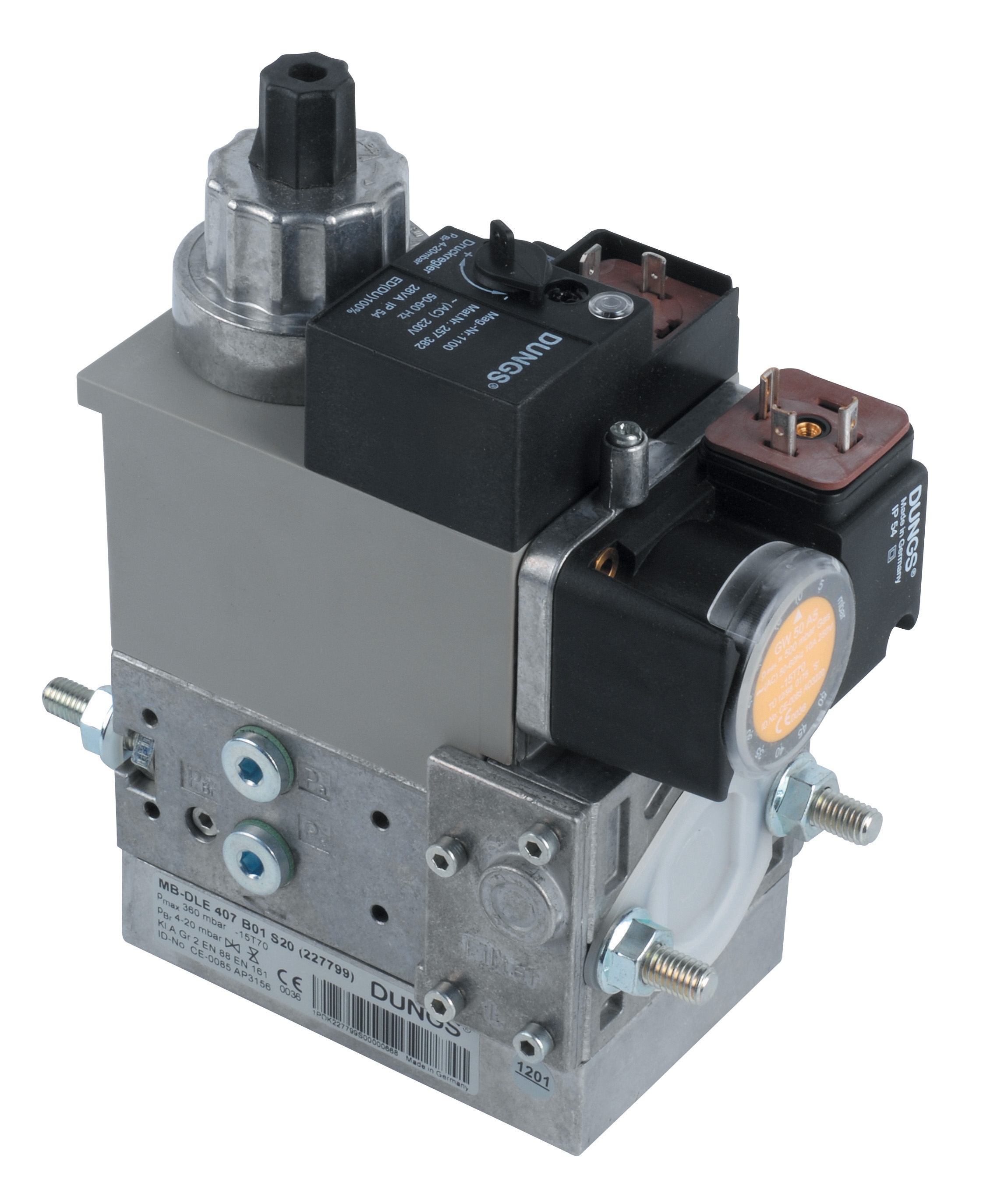
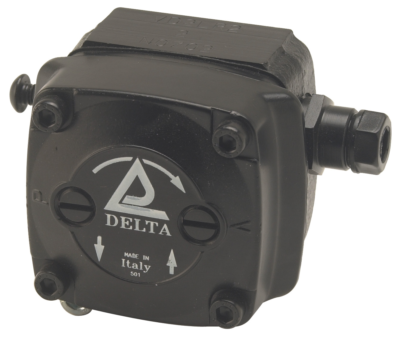
Modern industrial oil supply systems function as integrated units comprising three essential subsystems: the fuel pump, the pressure regulation mechanism, and the solenoid control circuit. The fuel pump—typically a positive displacement unit operating at 50–500 bar depending on application—draws fuel from storage and maintains consistent delivery pressure. The CBM VD2 LR-2.2 low-pressure pump exemplifies this category, engineered specifically for oil burner fuel units with integrated pressure regulation. This unit features high suction capability and self-priming functionality, making it suitable for both single and dual-pipe fuel systems common in Singapore industrial installations.
Pressure regulation occurs through spring-loaded relief valves or modulating regulators that maintain setpoint pressure while excess fuel returns to tank. Solenoid coils control fuel flow electrically, opening and closing valve ports in response to burner demand signals. Failure in any subsystem cascades through the entire chain: a degraded pump reduces pressure below setpoint, a stuck solenoid prevents fuel delivery regardless of pump condition, and a failed regulator creates pressure spikes that damage downstream components.
The diagnostic hierarchy follows this sequence: establish baseline electrical continuity and voltage at solenoid coils, measure actual system pressure against design specifications, quantify fuel flow rate at the nozzle, and finally inspect mechanical components for wear or contamination. This methodology prevents premature component replacement and identifies root causes rather than symptoms.
Technical Diagnostics: Pressure Testing, Flow Measurement, and Electrical Verification
Begin with electrical diagnostics at the solenoid coil level. Industrial systems typically operate on 230V AC or 24V AC control circuits. The CBM Coil 1930.1814 230V VML and CBM Coil 24V AC for ELV7 series represent standard industrial configurations. Using a digital multimeter, verify voltage supply at the coil terminals matches rated specification—230V ±10% or 24V ±10% for AC systems. If voltage is absent, trace the circuit upstream to the transformer or contactor. If voltage is present but the solenoid fails to energize (no audible click or mechanical response), the coil winding has failed and requires replacement.
Pressure testing requires calibrated gauges capable of reading the full system range. For low-pressure fuel systems, the CBM stainless steel axial manometer D63 0/+400 Mbar provides ±1.6% accuracy across the common 0–400 mbar industrial range. Install a test gauge directly at the pump discharge, with the burner in standby mode. Record static pressure (pump running, solenoid valve closed). This value should match the pump's design setpoint, typically 1.5–2.5 bar for burner systems. If static pressure falls below 80% of setpoint, the pump is degraded or cavitating due to suction-side blockage.
Next, measure dynamic pressure with the solenoid valve open and fuel flowing to the nozzle. Pressure drop across the open valve should not exceed 0.5 bar. Excessive drop indicates valve blockage or wear. For high-performance applications like the Interpump PUMP 5015 R ATEX—capable of 500 bar, 14.7 kW, and 15 L/min flow—pressure stability becomes critical. This unit operates at 1450 rpm and achieves 7250 psi peak pressure; any fluctuation exceeding ±5% suggests internal pump damage or contaminated fuel.
Flow measurement at the nozzle confirms system delivery capacity. Collect fuel output over 60 seconds and compare against design specification. A 20% flow reduction typically indicates pump wear, while near-zero flow with normal pressure suggests nozzle blockage. Digital vacuum gauges, such as the CBM BluVac, help identify vacuum-side issues by revealing suction-line restrictions or air leaks.
Real-World Application Scenarios: Case Studies from Singapore Industrial Operations
Scenario 1: Large-scale commercial heating installation using FBR X GAS XP 60 CE TC EVO methane burner (_41) with 232–630 kW output capacity experiences intermittent flame failure. Initial electrical testing confirms 3-phase supply voltage is present and stable. Pressure gauge installed at pump discharge reads 1.8 bar static pressure, within specification. However, when the burner reaches 50% modulation demand, pressure drops to 1.2 bar and flame extinguishes. Root cause: the pressure regulation cartridge inside the fuel unit has worn internal edges, allowing excessive bypass flow. Solution: replace the CBM VD2 LR-2.2 fuel unit as a complete assembly rather than attempting cartridge replacement, which consumes more labor than unit substitution in Singapore service environments.
Scenario 2: Industrial manufacturing facility operating a two-pipe fuel system with remote tank location reports fuel starvation during peak heating demand. Static pressure at pump discharge measures 0.9 bar versus 1.5 bar design specification. Suction-line vacuum gauge reading exceeds 0.8 bar, indicating excessive restriction. Inspection reveals tank strainer completely blocked with sediment. Pressure recovers to normal immediately after strainer cleaning. This case demonstrates how upstream system components (tank, suction piping, filters) are often overlooked during troubleshooting, yet cause 40% of fuel supply failures in Singapore's humid, particulate-rich industrial environment.
Scenario 3: Facility experiences erratic solenoid valve response and unreliable fuel shutoff. Voltage testing at the CBM ELK coil confirms correct 230V supply, but mechanical response is inconsistent. Inspection reveals corroded 7-pole male connector with oxidized contacts causing intermittent electrical continuity. Cleaning contacts or replacing the connector restores reliable solenoid operation. This highlights the importance of environmental protection in Singapore's tropical climate where salt spray and humidity accelerate electrical degradation.
Selection Criteria and Best Practices for System Reliability
When selecting fuel unit and pump components for new installations or replacements in Singapore industrial environments, prioritize matched-system specifications. The CBM VD2 LR-2.2 is engineered for burners requiring 1.5–2.5 bar regulation across flow ranges to 50 L/min. High-pressure applications exceeding 50 bar require external pump units such as Interpump TSX series units with integrated or external regulators. Cross-reference your burner's design fuel pressure, flow rate, and duty cycle (continuous, intermittent, or modulating) against pump and regulator specifications before purchase.
Material selection matters significantly in Singapore's corrosive atmosphere. Stainless steel gauge components (ROS23014) resist salt-spray degradation better than mild steel alternatives. Verify all electrical connectors feature marine-grade plating or stainless materials. Implement routine maintenance intervals: strainer inspection quarterly, gauge calibration annually, and solenoid coil resistance testing semi-annually. Document all pressure and electrical readings to establish baselines and detect gradual degradation trends before catastrophic failure.
Conclusion and Next Steps
Oil supply system troubleshooting requires disciplined methodology: electrical verification first, followed by pressure diagnostics, flow measurement, and mechanical inspection. By following this sequence, industrial professionals in Singapore can isolate root causes efficiently and minimize downtime. Whether diagnosing FBR burner fuel delivery issues, troubleshooting Interpump pump performance, or addressing solenoid coil failures, the core diagnostic framework remains constant.
3G Electric has served Singapore's industrial sector since 1990, maintaining inventory of CBM fuel units, Interpump pumps, solenoid coils, and precision pressure gauges required for these diagnostics. When you encounter oil supply system challenges, our technical team can verify component specifications against your system design and recommend replacement units matched to your operational requirements. Contact 3G Electric today to discuss your specific fuel system configuration or schedule diagnostic support from our experienced field service engineers.