Burners & Combustion: Diagnostic Testing, Performance Verification & Preventive Maintenance Protocols for Southeast Asian Industrial Operations
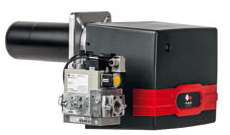
Table of Contentsexpand_more
Understanding Burners & Combustion System Diagnostics
Burners & Combustion systems represent one of the most critical infrastructure elements in industrial heating, power generation, and manufacturing operations throughout Southeast Asia. With over 35 years of experience distributing industrial equipment, 3G Electric has observed that most unplanned downtime and safety incidents stem not from catastrophic failures, but from inadequate diagnostic protocols and deferred preventive maintenance.
Unlike reactive repair approaches, systematic diagnostic testing enables maintenance teams to identify degradation patterns before they escalate to operational failures. The foundation of effective combustion system diagnostics rests on understanding that burner performance exists across measurable parameters: fuel pressure stability, air-fuel ratio precision, ignition reliability, and flame signal integrity. Each parameter can be quantified, trended, and compared against manufacturer baselines to predict component failure windows with remarkable accuracy.
Modern industrial burners operate as integrated control systems where sensors, actuators, and safety relays form interdependent networks. A pressure switch failure doesn't simply stop fuel delivery—it may disable modulation control, preventing the burner from responding to load changes. A flame detector degradation doesn't immediately trigger shutdown; it creates a window of vulnerability where the safety relay may not recognize unsafe combustion conditions. This systems perspective transforms maintenance from component replacement to strategic lifecycle management.
Diagnostic Testing Procedures and Field Measurement Protocols
Pressure and Flow Verification Testing
Begin with fuel delivery system diagnostics, the foundation upon which all combustion performance depends. Install pressure gauges at three critical points: inlet supply, post-regulator output, and burner nozzle inlet. Gas burners typically operate between 18-25 mbar for atmospheric-type units and 50-100 mbar for forced-air systems, while oil burners demand 80-120 bar atomizing pressure. The Kromschroder Pressure switch DG 50U/6 provides SIL 3-rated monitoring that can serve as reference baseline for manual gauge comparisons.
Measure pressure stability over a 10-minute operating cycle. Acceptable variance should not exceed ±2% from setpoint. Pressure oscillation exceeding 5% indicates either regulator wear, pump cavitation, or upstream supply contamination. Document these readings monthly and plot them on trend charts. When pressure begins drifting, you've identified a 6-8 week window before regulator replacement becomes necessary—far superior to waiting for burner shutdown.
For gas burners, conduct flowmeter testing using temporary orifice plates or ultrasonic flowmeters. Compare actual fuel consumption against manufacturer heat output specifications. A 10-stage burner delivering 30% less thermal output than nameplate capacity indicates either fuel supply restriction or nozzle degradation. Isolate the cause through staged testing: verify inlet pressure, measure outlet pressure across modulating valve, inspect nozzle orifice diameter with pin gauges.
Combustion Analysis and Efficiency Measurement
Portable combustion analyzers have become essential diagnostic tools for maintenance teams. Test burners under full-load conditions after 20 minutes of stable operation. Measure oxygen (O₂) content, carbon dioxide (CO₂), carbon monoxide (CO), and stack temperature simultaneously.
Gas burners should target 3-5% O₂ at the flue outlet (corresponding to approximately 10-11% CO₂). Readings above 6% O₂ indicate excess air, reducing efficiency and signaling air damper misalignment or fuel pressure deficiency. Readings below 2% O₂ indicate rich combustion with potential CO formation—especially dangerous in confined spaces common throughout Southeast Asian industrial facilities.
Carbon monoxide measurement is non-negotiable. CO levels above 100 ppm at the stack indicate incomplete combustion requiring immediate investigation. Causes range from air-fuel ratio deviation to burner blockage to flame impingement on heat exchanger surfaces. The Siemens Relay LFL 1.622 incorporates flame monitoring that detects such anomalies, but manual CO testing provides independent verification of combustion quality.
Stack temperature trending reveals heat exchanger fouling progression. Gas burners typically operate 150-200°C above incoming air temperature; increasing temperature deltas indicate soot accumulation reducing heat transfer efficiency. Oil burners show more dramatic temperature signatures. Schedule cleaning when stack temperature exceeds design baseline by 30°C, preventing efficiency loss and reducing maintenance emergencies during peak demand seasons.
Ignition and Flame Detection System Testing
Ignition system diagnostics require systematic component isolation. For burners using the Kromschroder Relay BCU 570WC1F1U0K1-E, conduct weekly manual ignition tests. Manually energize the ignition circuit with the burner in manual mode and fuel supply isolated. Observe ignition element heating—it should reach red-heat within 3 seconds. Measure ignition electrode voltage with a high-impedance multimeter; expect 3-5 kV for spark-type ignition and proper resistance for glow-type elements.
Flame detection presents the most critical diagnostic challenge. Burners employ either ionization sensing (measuring ion current in the flame) or ultraviolet sensing (detecting UV radiation). Both methods degrade over time through carbon fouling, internal electrode erosion, and optical surface contamination.
For ionization flame detectors, measure flame signal strength during normal operation. Signal should exceed 5 microamps under full-load conditions. Signals below 3 microamps indicate detector degradation; below 1 microamp triggers intermittent safety shutdowns. Clean detector electrodes with soft brass brushes—never abrasive materials. For UV detectors, clean lens surfaces with lens paper and optical-grade solvents monthly.
Conduct flame loss tests monthly: during normal operation, interrupt the flame by blocking fuel flow for 2-3 seconds. The burner safety relay should shut down fuel and ignition within 5 seconds. Failure to shut down indicates relay malfunction or flame detector signal loss. Both conditions require immediate component replacement—this is non-optional for safety compliance.
Preventive Maintenance Scheduling and Component Lifecycle Planning
Monthly Maintenance Tasks
Visual Inspection Protocol: Examine burner exterior, fuel supply connections, and electrical wiring for physical damage, leaks, or corrosion. In Southeast Asian climates with high humidity and salt-air environments (particularly coastal facilities), corrosion progresses rapidly. Apply light machine oil to external moving components. Inspect fuel lines for swelling (indicating incompatible elastomer materials) or cracking (pointing to age-related embrittlement).
Pressure and Flow Baseline Recording: Establish standardized measurement procedures. Record fuel pressure at identical ambient temperatures and load conditions. Compare against 12-month trend charts. Linear pressure reduction of 0.5 mbar/month is normal; acceleration beyond this indicates component degradation requiring investigation.
Safety Interlock Testing: Manually test safety shutdowns. Energize the burner, then simulate each safety condition: fuel pressure loss (close inlet valve), ignition failure (interrupt ignition supply), and flame loss (block fuel briefly). Document shutdown response times. Acceptable range: 3-5 seconds from condition detection to fuel shutoff.
Quarterly Maintenance Tasks
Fuel Filter Inspection and Replacement: Dirty fuel filters restrict supply pressure and cause modulation problems. Inspect filter element for color—tan indicates normal operation; black indicates water or carbon contamination requiring fuel system flushing; brown indicates biological contamination (common in tropical climates with high humidity). Replace filters quarterly in dusty environments, semi-annually in clean facilities.
Combustion Analysis and Efficiency Testing: Conduct full combustion analysis quarterly. Compare O₂, CO₂, CO, and stack temperature against baseline. Trending these parameters allows prediction of heat exchanger cleaning needs and identifies air-fuel ratio drift from valve stiction or sensor degradation.
Electrical Connection Verification: Southeast Asian humidity and temperature swings cause oxidation of electrical connections. Use calibrated multimeters to measure contact resistance at all terminals. Resistance above 0.1 ohm indicates corrosion requiring terminal cleaning and protective coating application. Tighten all electrical connections to manufacturer specifications—loose connections generate heat and trigger intermittent safety shutdowns.
Annual Maintenance Tasks
Complete Burner Disassembly and Cleaning: Remove burner from equipment. Inspect internal passages for carbon accumulation, soot deposits, and fuel gum formation. For oil burners, soak internal passages in approved solvents. For gas burners, use non-abrasive brushes. Measure nozzle orifice diameter with precision pin gauges; replace nozzles if diameter varies more than ±0.1 mm from specification.
Control System Component Replacement Schedule: Industry standards recommend replacing flame detectors every 2-3 years regardless of performance. Replace ignition electrodes every 3-5 years. Pressure switches like the Kromschroder Pressure switch DG 50U/6 should be verified for seal integrity annually and replaced at 10-year service life. Safety relays like the Kromschroder BCU 570WC1F1U0K1-E have 15-20 year design life but should undergo functionality testing annually.
Burner-to-Boiler Alignment Verification: Misalignment causes flame impingement and uneven heat transfer. Use precision alignment tools to verify burner nozzle positioning relative to furnace centerline. Misalignment beyond ±5 mm requires adjustment before the next heating cycle.
Predictive Maintenance Integration and Data-Driven Decision Making
Modern maintenance teams in Southeast Asia increasingly implement condition monitoring systems that transform burner diagnostics from scheduled events to continuous surveillance. Install permanent pressure transducers, temperature sensors, and oxygen analyzers connected to building management systems. These systems correlate burner parameters with facility demand, identifying inefficient operating windows and enabling load optimization.
For industrial facilities operating multiple burners—common in large manufacturing complexes across Southeast Asia—comparative analysis reveals performance divergence. When identical burners show 15% variance in thermal output despite similar operating hours, investigate the lower-performing unit immediately. Often this reveals developing failures that would remain invisible in single-burner facilities.
The FBR GAS XP 60/2 CE TC EVO and FBR KN 1300/M TL EL burners both support remote monitoring integration. Establish baseline performance parameters during commissioning, then monitor deviations. A 5% increase in modulation valve hysteresis, a 10% rise in ignition delay time, or a 2°C increase in flue temperature—individually minor—collectively signal imminent component failure. Predictive systems allow maintenance scheduling during planned downtime rather than reactive emergency response.
Document all diagnostic findings in standardized formats. Digital maintenance records create longitudinal performance databases that reveal component reliability patterns specific to your facility's fuel quality, ambient conditions, and operational profile. After 2-3 years of systematic data collection, maintenance teams can confidently predict component failure windows and optimize spare parts inventory accordingly.
![Gas Burner Types SG | Selection Guide [2026]](https://oxalncjenpflyqfncuhe.supabase.co/storage/v1/object/public/product-assets/products/907afddd-f10f-4f84-8526-06f1efc8daa0/002449_41.png)