Controls & Safety: Diagnostic Testing and Performance Validation Protocols for Singapore Industrial Burner Systems
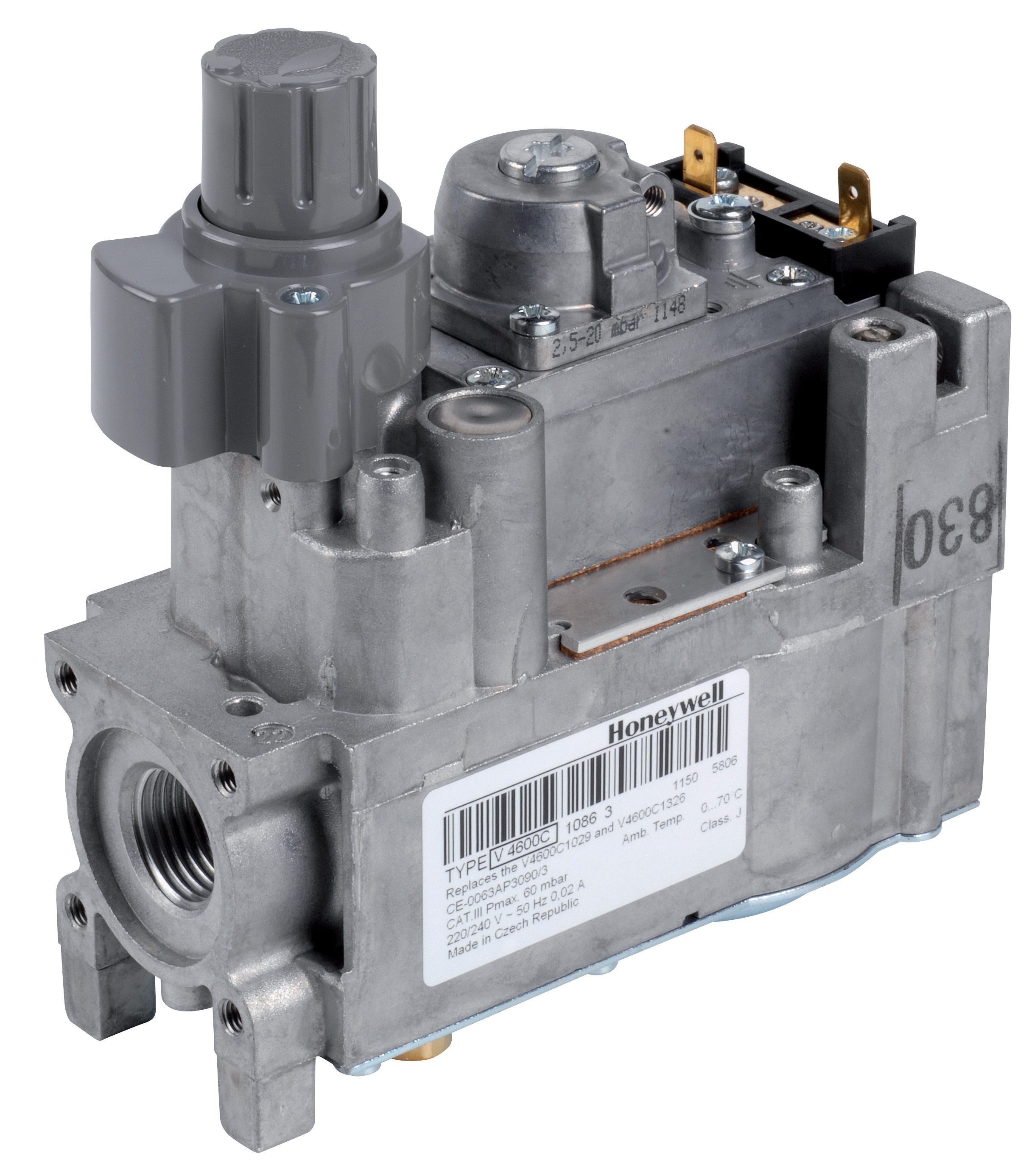
Table of Contentsexpand_more
Understanding Controls & Safety Diagnostic Requirements in Singapore Industrial Operations
Maintenance teams managing industrial burner systems across Singapore face critical responsibilities in validating Controls & Safety component functionality. Unlike routine maintenance tasks, diagnostic testing demands structured protocols that verify both electrical safety and combustion control integrity. Since 3G Electric entered the industrial equipment distribution market over 35 years ago, we've observed that preventive diagnostic testing reduces unplanned shutdowns by 40-60% and extends component lifecycle by 18-24 months.
The Singapore Standards Council and international compliance frameworks (EN 746-2, EN 676, EN 1854) establish baseline requirements, but practical field diagnostics require deeper understanding of component behavior under operational stress. Maintenance teams benefit from systematic approaches that isolate variables, confirm component functionality in isolation, then validate integration within the complete burner control circuit.
Controls & Safety systems comprise multiple interdependent elements—relays, pressure switches, solenoid valves, ignition modules, and flame detection sensors. A failure in any single component can trigger nuisance shutdowns, safety lockouts, or worse, uncontrolled combustion scenarios. Diagnostic protocols must therefore address each component category with appropriate testing methodologies, success criteria, and documentation standards.
Relay Testing and Flame Detection Module Validation
Burner control relays like the Kromschroder BCU 570WC1F1U0K1-E and the Siemens LFL 1.622 perform critical safety functions including flame monitoring, ignition sequencing, and shutdown triggering. Diagnostic testing for these components follows a hierarchical approach: bench testing in isolation, then integration testing within the burner control circuit.
Bench Testing Protocol for Control Relays:
- Visual inspection: Examine relay terminals, connector pins, and internal flame detection optics (UV windows or photo-resistive cells) for oxidation, corrosion, or physical damage. Even microscopic contamination on UV detection windows reduces flame signal acquisition by 15-30%.
- Continuity and resistance measurement: Use calibrated digital multimeters to verify terminal connections and measure coil resistance against manufacturer specifications. Abnormal resistance values typically indicate internal winding degradation or moisture ingress.
- Voltage supply verification: Confirm that control power supply voltage matches relay input specifications (typically 230V or 110V AC). Sustained under-voltage conditions cause nuisance lockouts during normal operation.
- Flame signal simulation: Many modern relays include test ports enabling technicians to simulate flame signals without actual combustion. The Siemens LFL 1.622 supports both UV and ionization flame monitoring; technicians should verify that the relay responds correctly to each detection type individually and confirm switchover time remains within specification (typically <10 seconds).
- Ignition output verification: Using appropriate isolation transformers and current-limiting devices, verify that relay ignition outputs provide required voltage and energy. The Pactrol Housing P 16 DI CE delivers 12 kV output with 10MJ energy; measure actual output values against specification limits. Output degradation below specification indicates internal component fatigue requiring relay replacement.
Once relays pass bench testing, integration diagnostics verify proper operation within the complete control system. Maintenance teams should conduct the following sequence:
1. Idle state verification: With fuel supplies isolated, confirm all relay outputs remain de-energized and no nuisance flame signals trigger ignition circuits. Record baseline electrical noise levels using oscilloscopes; excessive noise (>5% THD) indicates upstream supply quality issues.
2. Burner startup sequence: Execute full burner startup under controlled conditions, measuring timing intervals between each control sequence step. Excessive delays (>2 seconds) between ignition command and pilot flame confirmation may indicate slow relay response or inadequate fuel pressure.
3. Flame loss simulation: Deliberately extinguish pilot flames during operation and verify that the relay triggers immediate shutdown without extended hunting cycles. Proper operation typically shows shutdown within 5 seconds of flame loss.
4. Load shedding under fault conditions: Verify that relay outputs safely shed load when detecting abnormal conditions (reversed flame signal polarity, excessive flicker rate, sustained high combustion chamber pressure).
Pressure Switch Validation and Safety Integrity Verification
Pressure switches such as the Kromschroder DG 50U/6 function as critical safety interlocks in burner systems, preventing ignition during inadequate combustion air pressure and confirming proper draft conditions. Diagnostic testing for pressure switches encompasses both electrical functionality and mechanical reliability.
Mechanical Pressure Switch Testing:
- Calibration verification: Compare actual pressure switch trip points against manufacturer specification. The DG 50U/6 carries SIL 3 and Performance Level e ratings; deviations >5% from nominal trip pressure suggest mechanical wear requiring switch recalibration or replacement. Maintenance teams should use calibrated pressure gauges and manual hand pumps to establish pressure gradually, recording both rising-pressure and falling-pressure trip points to detect hysteresis anomalies.
- Repeatability testing: Execute minimum 10 pressure cycles through the trip point, documenting consistency of switch response. Variations >3% across cycles indicate mechanical stickiness or contamination in switch internals, requiring disassembly and cleaning or replacement.
- Port blockage inspection: Verify pilot and main pressure ports remain clear using compressed air (low pressure, <2 bar) without forcing debris deeper into passages. Blocked ports prevent proper pressure sensing and cause unsafe control logic.
- Housing seal inspection: Visual examination should confirm that pressure switch housing seals show no weeping or crystallized salt deposits. Seal failure allows moisture ingress, causing corrosion and unpredictable switch behavior.
- Contact resistance measurement: With the switch in both open and closed states, measure terminal resistance using micro-ohm meters (typically 0-50 mΩ for closed contacts, >10 MΩ for open contacts). Higher-than-spec resistance indicates oxidized contacts requiring replacement.
- Dielectric strength testing: Using appropriate high-voltage test equipment (typically 1500V AC for 230V rated devices), verify that switch contacts and housing withstand specified dielectric voltage without breakdown. This testing should occur every 24-36 months for critical applications.
Gas Control Block Integration and Solenoid Valve Sequencing
The Honeywell VK 4105 C 1041 U represents modern integrated gas control architecture, combining pressure regulation, metering, and solenoid switching in unified modules. Diagnostic testing for these components differs fundamentally from traditional relay-based systems, requiring pressure transducers and flow measurement equipment.
Gas Block Performance Validation:
- Pilot pressure verification: Measure pressure at pilot tap outlets (M8 x 1 pilot connections on VK 4105) using calibrated pressure gauges under no-flow conditions. Pilot pressure should stabilize within 10-15 seconds and remain within ±5% of setpoint during normal burner operation. Excessive pilot pressure causes pilot flame instability and ignition system strain.
- Main gas pressure regulation: With main burner firing, measure outlet pressure at the primary regulator outlet, comparing against setpoint specifications. Pressure regulation accuracy directly affects flame stability and burner turndown ratio. Poor regulation (<±5% across load range) indicates regulator poppet wear requiring module replacement.
- Feedback transducer calibration: Modern gas blocks include integral or external pressure feedback transducers enabling modulating control. Technicians should simulate burner load variations (by partially blocking combustion air inlet) and confirm that feedback pressure signals track actual outlet pressure without lag or oscillation. Response time should remain <2 seconds.
- Solenoid valve response time: Energize main gas solenoids and measure time to full opening (typically <3 seconds). Delayed or sluggish solenoid response indicates magnetic coil weakness or debris accumulation in valve orifices.
When gas control blocks operate with external relay controllers (like the Siemens or Kromschroder units), diagnostic testing must confirm proper signal conditioning and feedback loops:
- Modulation signal accuracy: If the burner system employs proportional or modulating control, measure analog feedback signals (typically 4-20mA current loops) comparing signal amplitude to actual combustion chamber pressure or main gas pressure. Signal drift >10% indicates transducer calibration drift requiring recalibration or replacement.
- Fail-safe valve sequencing: Verify that solenoid de-energization (loss of control signal) causes all gas valves to vent safely to atmosphere within 5 seconds. Extended vent times represent safety hazards in unattended burner operation.
Systematic Documentation and Trending Analysis
Maintenance teams managing Controls & Safety systems across multiple Singapore facilities benefit from structured documentation practices that enable predictive maintenance insights. 3G Electric's 35+ years serving industrial operations demonstrates that facilities maintaining baseline diagnostic data reduce emergency calls by 35-45% through early anomaly detection.
Recommended Documentation Framework:
- Equipment baseline record: Establish initial diagnostic test results immediately after component installation or major overhaul. Include measured values for all electrical parameters (coil resistance, contact resistance, control voltage), mechanical parameters (pressure switch trip points in both directions), and timing parameters (ignition sequence duration, flame detection response time).
- Trending spreadsheets: Record repeat diagnostic results at 6, 12, and 24-month intervals, enabling technicians to visualize parameter drift over extended periods. Gradual pressure switch drift at 0.3-0.5% per month, for example, suggests mechanical wear warranting replacement planning before failure occurs.
- Anomaly alert thresholds: Establish warning levels triggering technician investigation before parameters reach failure limits. Setting pressure switch calibration alerts at ±3% drift (vs. ±5% failure limit) provides 6-12 month advance notice, enabling scheduled replacement during maintenance windows rather than emergency repairs.
- Cross-facility benchmarking: For organizations with multiple burner installations, comparing diagnostic results across identical equipment reveals environmental factors (humidity, dusty conditions, thermal stress) affecting component lifecycle. This intelligence guides preventive maintenance intensity and component selection for new installations.
Practical Testing Equipment and Safety Considerations
Effective Controls & Safety diagnostics require appropriate instrumentation and strict adherence to safety protocols. High-voltage testing on energized circuits poses electrocution and arc flash hazards requiring PPE compliance and lock-out/tag-out procedures.
Essential diagnostic equipment includes:
- Digital multimeters with continuity and resistance measurement capability (minimum 2000-count resolution)
- Calibrated pressure gauges and manual hand pumps for pressure switch testing
- Oscilloscopes or power quality analyzers for voltage waveform analysis and harmonic content measurement
- Dielectric strength testers (hipot equipment) for periodic safety verification (1500V AC minimum)
- Current clamps and power meters for monitoring solenoid coil current during operation
- Thermal imaging cameras for identifying overheated relay components or poor electrical connections
- Complete fuel supply isolation and pressure venting before disassembling any pressure-containing components
- Lockout/tag-out procedures on control power supplies during bench testing
- Use of low-voltage flame simulators (not actual combustion) for relay testing in controlled environments
- Proper grounding and static discharge precautions when handling electronic relay modules
- Current-limiting devices protecting technicians during high-voltage testing
Maintenance teams unfamiliar with high-voltage or combustion system diagnostics should engage qualified service providers or equipment manufacturers for specialized testing, prioritizing safety over cost savings.
![Satronic Burner Controls SG | Buyer's Guide [2026]](https://oxalncjenpflyqfncuhe.supabase.co/storage/v1/object/public/product-assets/cbm/57d089e0-d3cf-4168-9f73-fb6bf7a7163b.jpg)