Introduction: Temperature Sensing in Controls & Safety Systems
Temperature control is fundamental to industrial HVAC and process heating systems, but its role in Controls & Safety extends beyond comfort regulation. In Singapore's demanding industrial environment, temperature sensors and thermostats function as critical safety interlocks—preventing over-temperature conditions, protecting equipment from thermal stress, and enabling burner shutdown sequences. Over 3G Electric's 35+ years as a distributor of industrial control equipment, we've supported thousands of installations where improper temperature sensing integration led to equipment failure, safety violations, or operational downtime.
This guide addresses a practical gap in industrial maintenance: how to properly integrate temperature-sensing devices into your control architecture while maintaining safety integrity. Whether you're commissioning new HVAC plant, retrofitting legacy systems, or troubleshooting temperature-related shutdowns, this technical walkthrough provides actionable procedures aligned with Singapore industrial standards.
Section 1: Temperature Sensor Selection and Circuit Design for Safety-Critical Applications
Choosing the Right Sensor Type
Industrial HVAC systems in Singapore typically employ three temperature-sensing technologies:
- Bulb thermostats (liquid-filled or gas-actuated) — mechanical sensors with electrical contacts triggered by thermal expansion
- Resistance thermometers (RTD) — precision electronic sensors requiring signal conditioning
- Thermocouples — high-temperature sensors used in burner flame zones and exhaust stacks
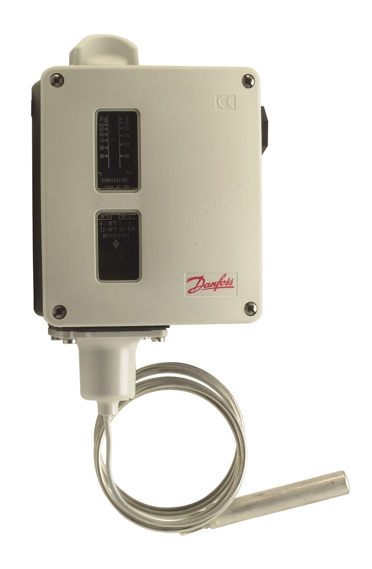
For general HVAC control and over-temperature protection, bulb thermostats remain the most robust choice in Singapore's humid, corrosive industrial environments. The Danfoss Thermostat RT 124 exemplifies this design: a single-pole changeover device with adjustable differential and neutral zone options, suitable for both heating and cooling control loops. Similarly, the Danfoss Thermostat RT 107 provides universal changeover contact design for temperature regulation in HVAC and industrial applications.
Circuit Integration Principles
Temperature sensors must be wired as part of a permissive logic chain—they enable or disable burner operation based on setpoint conditions. A typical circuit includes:
1. Temperature sensor contact (normally open or changeover)
2. Series connection in the burner enable circuit
3. Auxiliary contacts for alarm indication
4. Manual reset option for high-limit conditions
In Singapore's industrial code (adopted from IEC 61010 and EN 60730 standards), temperature sensors in safety-critical roles must be fail-safe: loss of sensor signal must result in safe shutdown, not continued operation. This requires normally-open contacts that prevent burner ignition if the thermostat becomes disconnected or fails mechanically.
Sensor Location and Installation
For HVAC systems:
- Setpoint thermostats mount in return air stream (minimum 0.5 m from fan discharge, away from direct solar radiation)
- Over-temperature thermostats mount in supply air duct, positioned to detect localized hot spots
- Exhaust thermostats mount 1–2 m downstream of burner exit to prevent false shutdowns from transient spikes
Minimum immersion depth is 75 mm for air-stream mounting. Use thermowells for accessibility and to allow field replacement without breaking system integrity.
Section 2: Thermostat Calibration, Setpoint Configuration, and Differential Adjustment
Pre-Installation Calibration Procedure
Before commissioning, verify thermostat accuracy against a certified reference thermometer:
1. Preparation: Obtain a precision digital thermometer (±0.5°C accuracy, NIST-traceable calibration certificate)
2. Immersion Test: Submerge both the thermostat and reference probe in a temperature bath at setpoint (e.g., 80°C). Wait 10 minutes for thermal equilibrium
3. Contact Verification: Confirm that the thermostat switches (makes or breaks contact) within ±2°C of rated setpoint
4. Multi-Point Check: Repeat at setpoint ±10°C to ensure linearity
5. Documentation: Record calibration data and attach certificate to control cabinet
In Singapore's tropical climate, do not perform calibration in ambient conditions—temperature swings between 25°C and 35°C will mask sensor errors. Always use a controlled thermal bath.
Differential and Hysteresis Configuration
Differential (or hysteresis) is the temperature deadband between sensor actuation and reset. For example, a thermostat set to 80°C with 5°C differential will:
- Energize burner when temperature falls to 75°C
- De-energize burner when temperature rises to 80°C
This deadband prevents relay chatter (rapid on-off cycling) that damages contactors and reduces component life.
Recommended differentials for Singapore HVAC systems:
- Comfort heating/cooling: 2–3°C (slow-response load)
- Process heating: 3–5°C (moderate response)
- Over-temperature protection: 5–10°C (prevents nuisance trips from transient spikes)
The Danfoss RT 124 offers field-adjustable differential via an internal screw; typical range is 2–15°C. Higher differentials reduce cycling energy but increase temperature overshoot. In Singapore's energy-conscious industrial environment, optimize for ±3°C regulation rather than tight ±1°C control, which increases maintenance burden without tangible benefit.
Neutral Zone Configuration
Some applications require a "dead zone" between heating and cooling setpoints—a temperature band where neither function is active. This prevents simultaneous heating and cooling (a major energy waste in tropical climates). The Danfoss RT 124 supports this via neutral zone adjustments:
- Set lower setpoint to 23°C (heating on below this)
- Set neutral zone offset to 3°C
- Upper contact activates at 26°C (cooling on above this)
- No active control between 23°C and 26°C
For industrial process applications in Singapore, a 3–5°C neutral zone is standard and reduces energy consumption by 8–12% compared to continuous cycling.
Section 3: Integration with Flame Detection and Burner Control Logic
Temperature Interlocking with Flame Safety Systems
Temperature sensors must coordinate with flame detection to create a coherent safety strategy. A typical sequence:
1. Ignition demand signal arrives (from thermostat or timer)
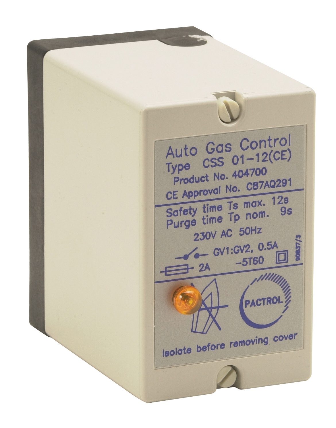
2. Spark generator initiates (part of Pactrol CSS01 control module or equivalent)
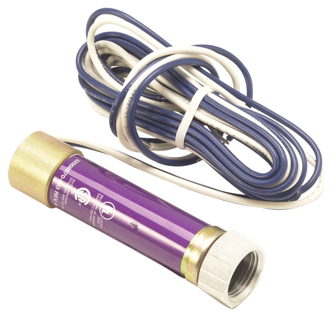
3. Flame detector (e.g., Honeywell Cell C 7044 A 1006 ultraviolet sensor) confirms combustion within 4 seconds
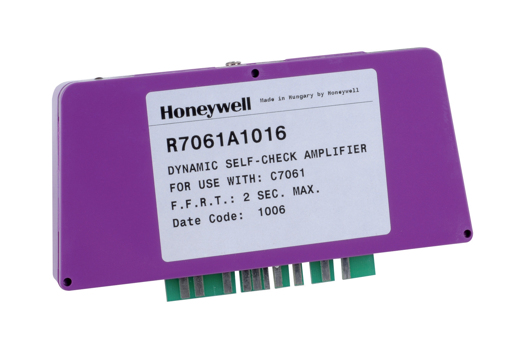
4. Amplifier (e.g., Honeywell R7861A 1026) outputs flame-proven signal
5. Temperature sensor contact must be closed to allow sustained burner operation
6. Over-temperature shutdown overrides all other signals if supply air exceeds setpoint
In Singapore's industrial environment, this interlock prevents a catastrophic scenario: a thermostat fails in closed position, burner runs indefinitely, over-temperature protection is the only safety net.
Commissioning the Temperature-Flame Logic
After wiring installation, perform this sequence:
Step 1: Static Test (Power Off)
- Verify thermostat contact at room temperature (should be open if setpoint is above ambient)
- Confirm continuity through thermostat contacts when manually pushed to setpoint condition
- Check for corrosion or oxidation on contact surfaces
- Enable burner control circuit
- Verify that burner does NOT fire if thermostat contact is open (safety-critical)
- Confirm that closing thermostat contact allows spark generation to commence
- Verify that flame detector responds within 4 seconds of spark initiation
- Operate burner in heating mode
- Use an external temperature probe to monitor supply air rise
- Confirm that at over-temperature setpoint (e.g., 90°C), burner shuts down automatically
- Verify that temperature drops ≥5°C before relight cycle can resume
- Simulate thermostat failure (disconnect sensor or manually open contact)
- Burner must shut down within 2 seconds
- Confirm no automatic restart for minimum 30 seconds
These tests must be documented on a commissioning checklist and retained for regulatory audit.
Section 4: Maintenance, Troubleshooting, and Compliance in Singapore Industrial Standards
Preventive Maintenance Schedule
Monthly:
- Visual inspection of thermostat for condensation or corrosion inside sightglass
- Listen for "clicking" from thermostat during operation—indicates metallic debris in bulb, requiring replacement
- Check calibration chart on control cabinet; compare logged setpoint against nameplate
- Clean thermostat sensing bulb with soft cloth and mild isopropyl alcohol (if accessible)
- Verify that all wiring terminals remain tight (vibration in industrial HVAC systems can loosen connections)
- Test setpoint accuracy against handheld thermometer at two points (±10°C from nominal)
- Full calibration against certified reference thermometer (as described in Section 2)
- Replace thermostat if drift exceeds ±3°C
- Inspect thermowell for blockage or scale buildup; clean with warm water and soft brush
Troubleshooting Common Temperature Control Faults
Burner fires continuously, ignoring thermostat setpoint
- Thermostat contact stuck in closed position → replace thermostat
- Wiring short across thermostat terminals → inspect and repair wiring
- Control module relay seized → test relay with ammeter; replace if current does not drop to zero when thermostat opens
- Differential setting too narrow → increase to minimum 3°C
- Thermostat bulb in air current (e.g., near duct opening) → relocate to centerline of duct
- Sensor fouling or scale → clean or replace thermowell
- Sensor reading high (cooler air is sensed as warmer) → verify probe immersion depth and position
- Burner fuel line blockage → check fuel pressure at burner (beyond scope of temperature control, but confirm setpoint is achievable)
- Control module contact resistance high → measure contact voltage drop under load; if >0.5 V, replace contact block
Compliance with Singapore Industrial Standards
Industrial HVAC systems in Singapore must comply with:
- PUB Code of Practice for Energy Efficiency (industrial): Requires temperature control accuracy within ±3°C for process loads and ±2°C for comfort HVAC
- SS 638 (Singapore Standard for Safety of Pressure Equipment): Applies if thermostat controls pressurized systems; temperature sensors must be on both supply and return for balanced control
- EN 60730-2-9 (Automatic Electrical Controls): De facto standard adopted by Singapore industrial inspectors; temperature sensors must fail-safe and be accessible for testing
Before commissioning, obtain a signed compliance certificate from your controls contractor confirming:
1. Thermostat calibration records
2. Setpoint and differential selections documented
3. Safety shutdown test results
4. Maintenance schedule posted on control cabinet
3G Electric, as a distributor of industrial control components for over 35 years, recommends maintaining these records for the life of the equipment—at minimum 10 years in Singapore industrial operations.
Conclusion
Temperature sensing and thermostat integration are not "set and forget" functions. In Singapore's high-humidity, vibration-prone industrial environment, proper calibration, strategic differential adjustment, and coordinated safety interlocking are essential to reliable HVAC operation. By following the procedures outlined here—from pre-commissioning calibration through quarterly maintenance—you will eliminate unnecessary burner cycling, extend equipment life, and ensure that over-temperature protection functions as intended when critical faults occur.
For assistance selecting thermostats and controls suited to your specific HVAC application, contact 3G Electric's technical team with details of your system capacity, operating temperature range, and safety requirements.