Understanding Integrated Temperature and Flame Detection Control Architecture
Controls & Safety in modern industrial burner systems depends on the synchronized operation of temperature sensing and flame verification equipment. Unlike simple on-off burner controls, integrated architectures use temperature feedback to regulate firing intensity while flame detection serves as an independent safety interlock.
In Southeast Asian industrial facilities—where high ambient temperatures, humidity, and vibration present unique challenges—proper integration of these systems is critical. A thermostat measures process temperature and sends modulation signals to the burner controller, while a flame detector independently verifies that combustion is actually occurring. If either system fails, the burner must shut down safely.
During our 35+ years serving Asia-Pacific industrial markets, 3G Electric has observed that most burner failures result not from individual component defects, but from poor integration between temperature control and flame monitoring subsystems. This guide provides actionable procedures to avoid these integration failures.
System Selection and Component Compatibility
Selecting the Right Temperature Control Device
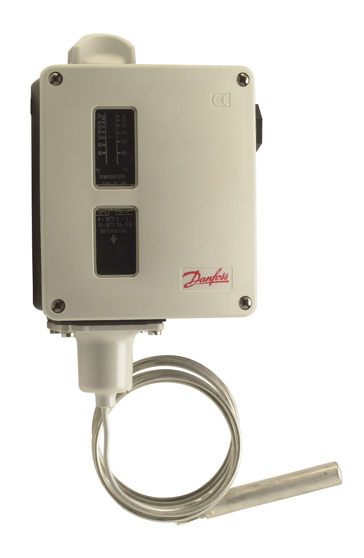
Temperature control in industrial burner systems typically begins with a bulb-actuated or electronic thermostat. The Danfoss RT 124 thermostat provides single-pole changeover contact operation with adjustable differential settings—essential for preventing hunting (rapid on-off cycling) in tropical climates where ambient conditions fluctuate rapidly.
For Southeast Asian applications, consider these selection criteria:
- Differential Setting: In humid tropical environments, set differential 2–3°C higher than in temperate regions to account for slower thermal response times
- Neutral Zone: Enable neutral zone functionality to prevent short-cycle operation during load transitions
- Contact Rating: Verify that the thermostat's electrical contacts can safely control the flame detector amplifier's input circuits
The Danfoss RT 107 offers universal single-pole changeover contacts suitable for both heating and cooling applications, making it ideal for facilities operating multiple burner zones with different temperature requirements.
Selecting Flame Detection and Amplification Equipment
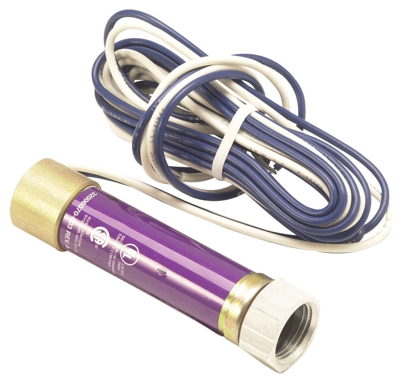
Flame detection operates as an independent safety layer. The Honeywell Cell C 7044 A 1006 ultraviolet flame detector detects UV radiation from combustion, providing reliable response regardless of thermostat position.
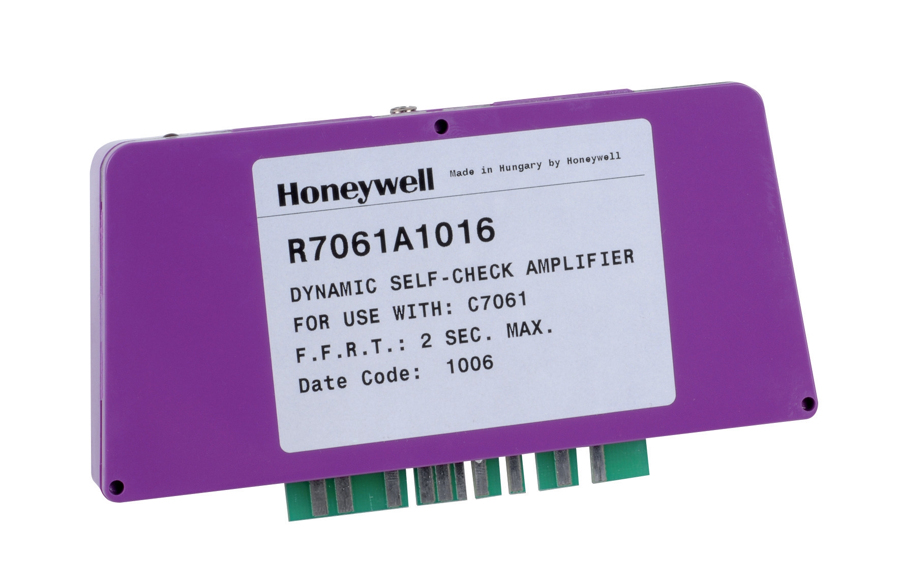
The flame detector's signal is extremely weak—typically 5–10 microamps—and must be amplified before triggering safety interlocks. The Honeywell Amplifier R 7861 A 1026 is specifically designed for this purpose, operating across the –40°C to 60°C range common in Southeast Asian industrial facilities and withstanding continuous 0.5 g vibration typical of mechanical plant environments.
Critical compatibility check: Ensure the flame detector's tube diameter (1 inch for the Cell C 7044) fits your burner's viewing port before purchasing. Mismatches require expensive burner modifications.
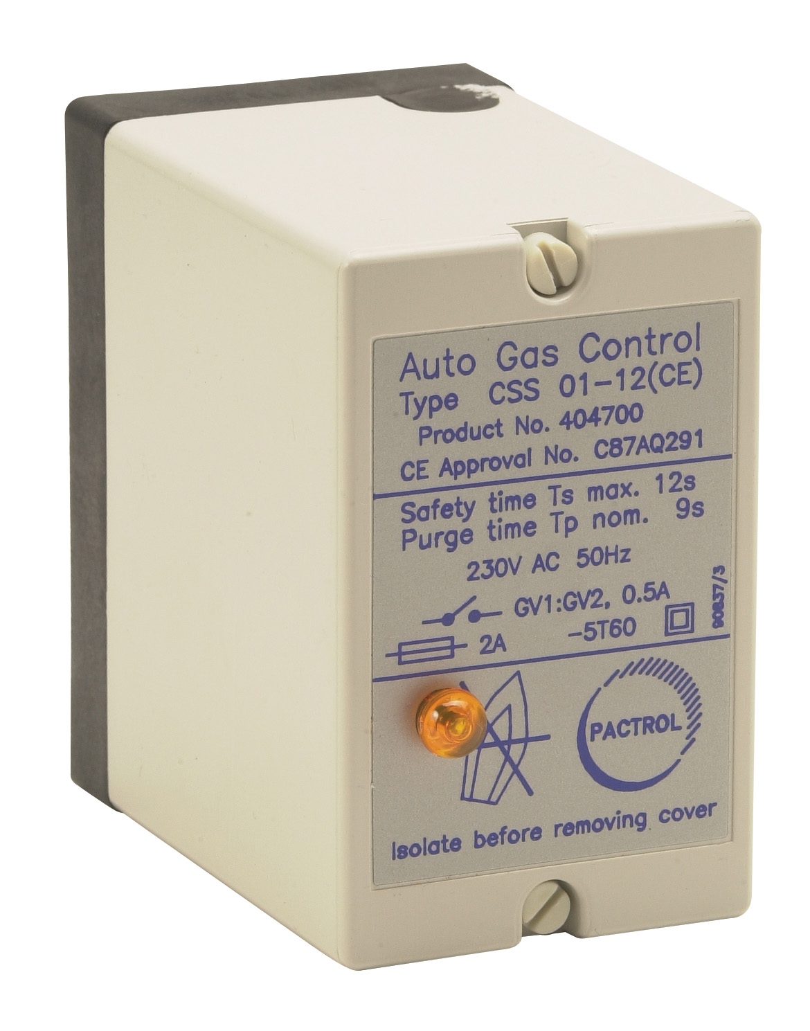
Integration Hub: The Burner Control Module
The Pactrol CSS01 control module consolidates thermostat input, flame detection signals, and ignition sequencing into a single integrated control unit. This module is rated for atmospheric and forced-air burners up to 60 kW—suitable for most Southeast Asian HVAC and process heating applications.
The CSS01 integrates three critical functions:
- Timed Relay: Manages ignition timing and prevents false starts
- Flame Relay: Continuously monitors the flame detector amplifier output
- Electronic Spark Generator: Produces reliable ignition regardless of fuel type (oil or gas)
This consolidation reduces wiring complexity and potential integration failure points.
Commissioning Integrated Temperature and Flame Detection Systems
Pre-Commissioning Verification
Before powering any system, perform these checks:
1. Thermostat Continuity: Use a multimeter to verify that the temperature control thermostat's changeover contacts open and close smoothly across the expected operating range (typically 40–80°C). In humid environments, contacts may stick—clean with isopropyl alcohol if necessary.
2. Flame Detector Viewing Path: Ensure the UV sensor cell faces the flame without obstructions. A single dust particle can reduce signal strength by 30–50% in tropical installations where dust accumulation is rapid. Position detectors away from oil mist and exhaust plumes.
3. Amplifier Power Supply: Verify that the Honeywell R 7861 A 1026 amplifier receives stable 115 VAC or 230 VAC (confirm voltage before connection). Southeast Asian electrical systems often experience ±10% voltage fluctuations; the amplifier tolerates this but marginal power supplies will cause intermittent flame failures.
4. Control Module Wiring: Check all terminations to the Pactrol CSS01 for loose connections. Vibration in HVAC equipment loosens terminals within 2–3 weeks of operation if not properly secured.
Cold Commissioning (System Off)
With power disconnected:
- Trace all signal wiring from thermostat → control module → flame amplifier → burner
- Verify polarity for DC signal circuits (reverse polarity will prevent flame detection)
- Measure wiring insulation resistance (minimum 1 megohm between any signal wire and ground)
- Check thermostat calibration by comparing bulb temperature reading to a reference thermometer
Hot Commissioning (System Operating)
Step 1: Establish Baseline Flame Signal
Start the burner without any load. The flame detector should immediately output a signal (typically 3–5 mA) to the amplifier. Use a clamp meter to measure this current. If the signal is below 2 mA, the flame detector is either misaligned, contaminated, or facing an obstruction.
Step 2: Verify Thermostat Integration
Set room temperature 3°C above the thermostat setpoint. The thermostat should complete its changeover contact, permitting the control module to initiate burner startup. Observe the flame relay—it should energize within 3 seconds of flame establishment.
If the relay fails to energize despite visible flame, the amplifier may be defective or the signal wiring may be reversed. Do not operate the system further; troubleshoot before proceeding.
Step 3: Load Test and Modulation
With the burner running, allow room/process temperature to approach the thermostat setpoint. The thermostat should gradually open its contact, signaling the control module to reduce firing intensity. This modulation cycle should be smooth—not hunting or cycling.
In Southeast Asian humid environments, expect modulation to be slower than in temperate zones. Allow 2–3 minutes for thermal system response before concluding malfunction.
Step 4: Flame Stability Monitoring
Observe flame detector signal stability over 15 minutes of continuous operation. The signal should remain constant (±10%) unless room/process load changes. Fluctuating flame signals indicate:
- Burner nozzle wear
- Fuel supply pressure variations
- Air shutter misalignment
- Contaminated fuel filter
Operational Validation and Seasonal Maintenance
Daily Operational Checks
Industrial professionals should perform these checks at shift start:
1. Visual Flame Inspection: Observe burner flame color and stability. Yellow or orange flames indicate incomplete combustion; adjust air shutter or fuel pressure.
2. Thermostat Response: Manually lower room setpoint 2°C. The burner should respond within 30 seconds. If delay exceeds 60 seconds, the thermostat may be fouled or thermally unresponsive.
3. Flame Detector Status Light: Most amplifiers (including the Honeywell R 7861) include an LED that blinks during normal flame detection. A steady light or no light indicates malfunction.
Pre-Season Maintenance (Before Cooling/Heating Seasons)
Southeast Asia's transition seasons create rapid temperature swings that stress control systems:
- Clean Thermostat Bulb: Wipe the sensing bulb with a soft, dry cloth. Do not use solvents.
- Inspect Flame Detector: Remove any dust, spider webs, or debris from the UV sensor cell. Use compressed air (not liquid cleaning agents) to blow dust away from the cell window.
- Verify Control Module Contacts: Inspect the Pactrol CSS01 terminals for green oxidation (corrosion common in humid climates). Clean with a pencil eraser if necessary.
- Test Emergency Shutdown: Confirm that the flame detector amplifier can shut down the burner when its signal is interrupted (unplug the detector briefly while burner is running; it should flame-out within 2 seconds).
Troubleshooting Integrated System Failures
Burner starts but flame detection fails to lock in:
The flame detector is not receiving signal. Check: (1) UV sensor pointing at flame; (2) tube window cleanliness; (3) amplifier power supply voltage; (4) signal wiring polarity to amplifier input. The Honeywell R 7861 A 1026 is reverse-polarity sensitive.
Burner cycles on-off every 2–3 minutes (short-cycling):
The thermostat differential is too narrow for tropical humidity conditions. Access the thermostat (RT 124 or RT 107) and increase differential setting by 1–2°C. Alternatively, verify that the control module's timed relay is not set too short (minimum 3-minute burn time typical).
Thermostat reaches setpoint but burner doesn't modulate down:
The thermostat's changeover contact may be stuck. Tap the thermostat gently (not forcefully) while observing the control module's response. If the burner suddenly throttles, the contact is adhesive and requires cleaning.
Compliance and Risk Management
Most Southeast Asian jurisdictions (Singapore, Malaysia, Indonesia, Thailand) require industrial burner systems to have independent flame detection—not optional. The integrated architecture described here meets these requirements by:
- Maintaining flame detection as a separate safety circuit (the amplifier operates independently of the thermostat)
- Ensuring safe shutdown if either the temperature control or flame detection fails
- Providing auditable operational logs (control modules record cycle times and fault events)
When specifying equipment through 3G Electric, ensure purchase orders explicitly reference the flame detector amplifier model (R 7861 A 1026) and not just the detector cell. Many integration failures result from receiving a detector without its matching amplifier.
Documentation is critical: maintain a controls schematic showing thermostat connection points, amplifier signal input polarity, and burner shutdown circuit paths. In tropical environments, environmental humidity and mold growth can obscure wiring over time. Clear, laminated schematics posted near equipment reduce troubleshooting time and improve safety response during emergencies.