Controls & Safety: Installation and Commissioning Best Practices for HVAC Burner Systems in Singapore
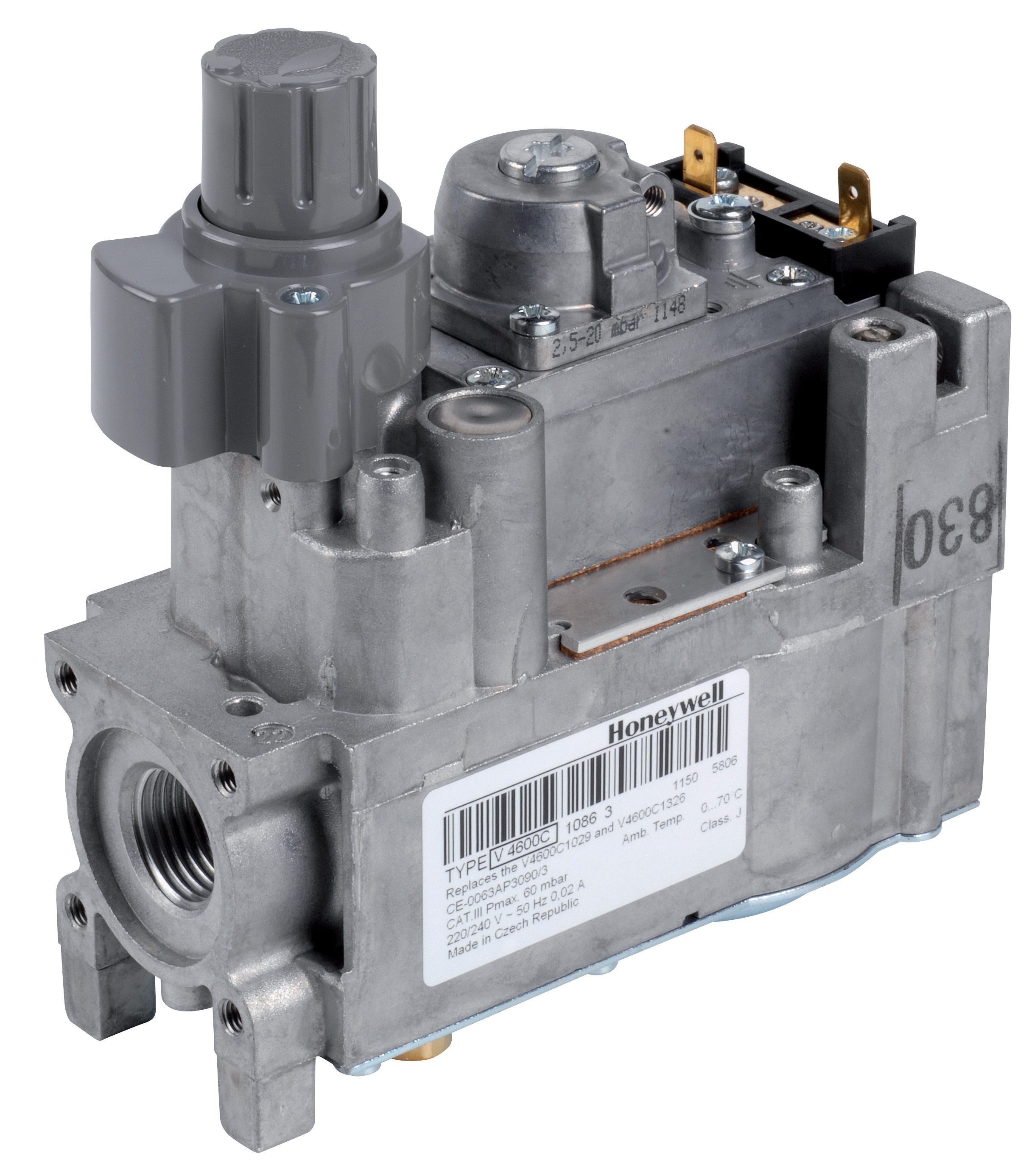
Table of Contentsexpand_more
Understanding Controls & Safety Installation Requirements
Controls & Safety systems form the critical foundation of any industrial HVAC burner installation. Unlike troubleshooting or maintenance guides, this article focuses on the often-overlooked installation phase—where most system reliability issues originate. With over 35 years of experience distributing industrial equipment across Southeast Asia, 3G Electric has observed that installation quality directly impacts system performance, compliance, and longevity.
For HVAC contractors in Singapore, understanding the proper installation sequence, wiring practices, and commissioning protocols is essential for regulatory approval and customer satisfaction. Singapore's stringent building codes and safety standards require meticulous attention to installation detail. This guide walks you through the practical steps needed to install Controls & Safety components correctly the first time.
Section 1: Pre-Installation Planning and Component Verification
Site Assessment and Equipment Layout
Before any component arrives on site, conduct a thorough assessment of the burner installation space. Identify mounting locations for control relays, pressure switches, and gas block valves that minimize vibration exposure and maintain safe distances from heat sources. In Singapore's humid tropical climate, ensure adequate ventilation around electrical enclosures to prevent moisture ingress and corrosion.
Verify that your installation space accommodates the physical dimensions and connection requirements of selected components. For example, the Kromschroder Relay BCU 570WC1F1U0K1-E requires sufficient clearance for terminal access and pilot ignition leads. Document the burner's fuel type (gas, oil, or dual-fuel) and flame monitoring method before purchasing controls.
Component Specification Checklist
Confirm that all Controls & Safety components meet Singapore's relevant standards:
- Pressure switches should comply with EN 1854 and carry SIL 3 ratings for critical applications. The Kromschroder Pressure switch DG 50U/6 meets these requirements for burner control applications.
- Control relays must support your burner's ignition mode (direct ignition, intermittent pilot, or continuous pilot). Verify EN 746-2 and EN 676 compliance as standard.
- Gas control blocks need appropriate pressure ratings and modulation capability. The Honeywell Gas block VK 4105 C 1041 U provides electric modulation across standard operating ranges.
- Flame detection modules should match your flame detection technology (UV, ionization, or infrared). The Pactrol Housing P 16 DI CE delivers 12 kV ignition output with 10MJ energy—adequate for most industrial applications.
Request datasheets for all components and cross-reference terminal designations, voltage requirements, and pressure ratings before installation begins. This step prevents costly field modifications and delays.
Section 2: Electrical Integration and Wiring Installation
Control Panel Layout and Safety Interlocking
Design your control panel layout to segregate power circuits, signal circuits, and flame detection circuits. This separation prevents electromagnetic interference and ensures signal integrity for safety-critical functions. Allocate dedicated space for the Siemens Relay LFL 1.622, which serves as your primary safety control unit for medium to high-power burners.
When mounting control relays in the panel, position them away from high-current terminals and power distribution components. Use DIN rail mounting where possible to simplify installation and future maintenance. Ensure all mounting hardware is stainless steel or corrosion-resistant to withstand Singapore's saline atmosphere, particularly for installations near coastal areas.
Pilot and Main Flame Sensing Circuit Installation
Flame sensing circuits represent the most safety-critical portion of Controls & Safety installation. Install flame sensor leads in separate conduit from power wiring—never run them in the same cable bundle. Use shielded cable for all flame detection circuits, with shield grounding only at the control relay terminal.
For systems using the Kromschroder Relay BCU 570WC1F1U0K1-E, carefully route pilot ignition leads to avoid sharp bends and physical stress. Pilot leads carry high voltage (typically 10-12 kV) and require careful bend radius management (minimum 50mm radius for most cable types). Secure pilot leads with non-conductive clips at 300mm intervals to prevent vibration-induced failure.
Connect flame detection sensors (thermocouple or UV/ionization detector) directly to control relay input terminals with minimal lead length. Long lead runs introduce signal degradation and false flame loss detection. If lead length exceeds 2 meters, consult the control relay manufacturer for signal conditioning requirements.
Pressure Switch Wiring and Configuration
The Kromschroder Pressure switch DG 50U/6 connects to your control circuit as either a normally open (NO) contact for high-pressure detection or normally closed (NC) contact for low-pressure detection. Verify which configuration your system design requires—this determines correct terminal connection.
Run pressure switch wiring through separate conduit from pilot ignition leads. Use 0.75–1.5 mm² cable rated for your panel voltage (typically 230V AC or 24V DC control circuits). Avoid tight cable routing around the pressure switch body; provide 100mm of slack to accommodate pressure switch movement during operation.
Section 3: Pneumatic and Hydraulic Component Installation
Pressure Gauge Installation and Regulation
Before connecting the Honeywell Gas block VK 4105 C 1041 U to main fuel supply, install a pressure gauge on the supply line upstream of the gas block. This gauge allows you to monitor incoming fuel pressure during commissioning and operation. Install the gauge with a ball valve isolation point so you can remove it for calibration without shutting down the entire burner.
Set the gas block modulating valve to its mid-position during initial startup. This prevents sudden fuel flow surges that might damage the burner or trip safety interlocks. The Honeywell gas block's M8 × 1 pilot connection requires precise threading—hand-tighten first, then use only 1–1.5 turns with a wrench to avoid over-torque damage.
Pilot and Main Fuel Line Purging
After all pneumatic connections are complete, purge air from pilot and main fuel lines. For gas systems, use the gas supply itself to purge—slowly open the fuel shut-off valve and allow gas to flow at low pressure for 2–3 minutes until no air bubbles appear at the burner pilot jet. Never pressurize the system beyond its design rating; refer to component datasheets for maximum safe pressures.
Install shut-off ball valves at all critical fuel supply points: upstream of the pressure switch, upstream of the gas block, and at the pilot supply line. These valves allow you to isolate components during troubleshooting or maintenance without affecting the entire burner installation.
Pressure Switch Calibration Points
Before final commissioning, identify and mark the pressure points where your pressure switches activate. For the Kromschroder Pressure switch DG 50U/6, this typically occurs at 0.1–0.5 bar above normal operating pressure. Use your upstream pressure gauge to verify switch activation during low-fire and high-fire operation. Document these values in your commissioning report for future reference.
Section 4: Commissioning Procedures and Safety Verification
Flame Detection System Verification
Before igniting the burner, verify that flame detection circuits respond correctly to test signals. Many control relays, including the Siemens Relay LFL 1.622, incorporate flame signal simulation features for testing without actual combustion.
Activate the flame simulation mode (consult your control relay manual for the specific procedure) and confirm that the control relay recognizes the simulated flame signal. The relay should transition from "flame loss" to "flame detected" state. Record the flame signal voltage at the control relay input—this establishes a baseline for future troubleshooting.
Test flame loss response by interrupting the flame signal while the burner operates at pilot light. The control relay should trigger a burner shutdown sequence within 2–5 seconds, depending on your control relay's safety rating (typically SIL 2 or SIL 3).
Ignition System Testing
With the Pactrol Housing P 16 DI CE installed, verify that the ignition output voltage reaches the burner's spark plug electrodes. Use an insulated probe and high-voltage meter to measure output voltage at the ignition electrode—it should match the housing's rated output (12 kV for the Pactrol unit). Never touch the ignition output terminal with bare hands; 12 kV output creates serious shock hazard.
Confirm that ignition energizes only when the burner control sequence calls for pilot light ignition. Run through a complete startup cycle (off → ignition on → pilot light → main fuel) and monitor the control relay's response at each stage. Any deviation from expected sequencing indicates a wiring or component configuration error that requires resolution before full operation.
Safety Interlock Verification
Test all safety interlocks in sequence:
1. Proof of ignition: Verify that the burner shuts down if flame is not detected within 5 seconds of ignition startup.
2. Pressure switch operation: Confirm low-pressure and high-pressure switches activate at their calibrated setpoints.
3. Pilot light proving: For systems using intermittent or continuous pilot ignition, verify that the burner cannot reach main fuel stage without a stable pilot flame.
4. Manual reset: Test the manual reset function on your control relay to ensure operators can safely respond to nuisance shutdowns.
Document the response time for each safety function. Fast response times (< 1 second) indicate proper signal transmission; slower responses may suggest wiring impedance issues or loose connections requiring attention.
Load Testing and Stable Operation
Run the burner through multiple startup and shutdown cycles while monitoring fuel consumption, flame stability, and thermal output. On the first cycle, set fuel supply to 50% capacity and observe the burner's response. Increase to full load only after confirming stable, steady flame at reduced output.
Monitor the control relay and pressure switch operation throughout the test cycle. All components should respond smoothly without chatter (rapid switching) or hunting (oscillation between states). If you observe component chatter or instability, reduce load by 10% and test again. Instability at full load often indicates oversized or poorly tuned fuel control components requiring adjustment or replacement.
After successful load testing, allow the burner to cool and perform a final visual inspection of all electrical connections, pilot lines, and fuel supply lines. Look for leaks, loose terminals, or damaged insulation. Tighten any loose connections discovered during cooling inspection and repeat the load test to confirm stability.
Commissioning Documentation
Complete a detailed commissioning report documenting:
- Component serial numbers and installation dates
- Pressure switch calibration values (low and high setpoints)
- Flame signal voltage measurements at control relay input
- Ignition system output voltage verification
- Safety interlock response times
- Load test results at 50%, 75%, and 100% capacity
- Any adjustments or modifications made during commissioning
- Date of next scheduled maintenance
Provide this report to the building owner and retain a copy for your installation records. In Singapore, building regulators may request commissioning documentation as evidence of proper installation compliance with building codes.
Best Practices from 35 Years of Industrial Distribution
Through decades of supporting HVAC contractors across Southeast Asia, 3G Electric has observed that successful Controls & Safety installations share common characteristics:
- Thorough pre-installation planning: Sites that invest time in layout design and component verification experience fewer field modifications and faster commissioning.
- Proper cable management: Separating power, signal, and pilot circuits prevents electromagnetic interference and simplifies future troubleshooting.
- Meticulous pressure calibration: Pressure switches properly calibrated to your specific burner characteristics eliminate false shutdowns and nuisance alarms.
- Comprehensive commissioning testing: Thorough testing at each stage (electrical, pneumatic, ignition, safety) identifies issues while they're still simple to correct.
- Complete documentation: Detailed commissioning records become invaluable references during future maintenance and troubleshooting.
By following these installation and commissioning procedures, HVAC contractors ensure that Controls & Safety systems operate reliably throughout their service life, meeting Singapore's regulatory standards and customer expectations for performance and safety.

![Satronic Burner Controls SG | Buyer's Guide [2026]](https://oxalncjenpflyqfncuhe.supabase.co/storage/v1/object/public/product-assets/cbm/57d089e0-d3cf-4168-9f73-fb6bf7a7163b.jpg)