How to Troubleshoot and Optimize Gas Valve Performance in Industrial Burner Systems
Gas valve failures and suboptimal performance directly impact burner efficiency, production uptime, and operational costs in industrial facilities across Singapore. While proper installation is critical, understanding how to diagnose valve malfunctions and optimize system performance separates competent maintenance teams from exceptional ones. This guide provides actionable troubleshooting methodology and optimization strategies specific to industrial gas regulation systems, enabling you to identify root causes, implement targeted solutions, and maintain peak burner performance. Whether you're managing a single burner or complex multi-burner installations, these diagnostic techniques will help minimize downtime and extend equipment lifespan.
Understanding Gas Valve Failure Modes and Performance Degradation
Gas valve performance issues rarely occur without warning. Understanding the primary failure modes enables predictive maintenance and rapid diagnosis when problems arise. The most common performance degradation patterns in industrial solenoid and modulating valves include pressure drift, flow inconsistency, delayed response times, and complete blockage.
Pressure-related failures occur when system pressure deviates from design specifications. Over-pressurization can damage internal valve seals and reduce valve lifespan, while under-pressurization prevents proper valve operation. In Singapore's humid industrial environment, moisture ingress into pressure lines accelerates corrosion and deposits that restrict flow pathways. This is particularly critical in systems operating at low differential pressures—below 0.5 bar—where even minor blockages significantly impact valve authority.
Flow inconsistency manifests as unstable burner flames, irregular heat output, or hunting (oscillating) modulation. This typically results from contamination in valve ports, degraded solenoid coil performance, or calibration drift in modulating valves. Industrial gas supplies often contain particulates, water vapor, and sulfur compounds that accumulate in valve passages over time.
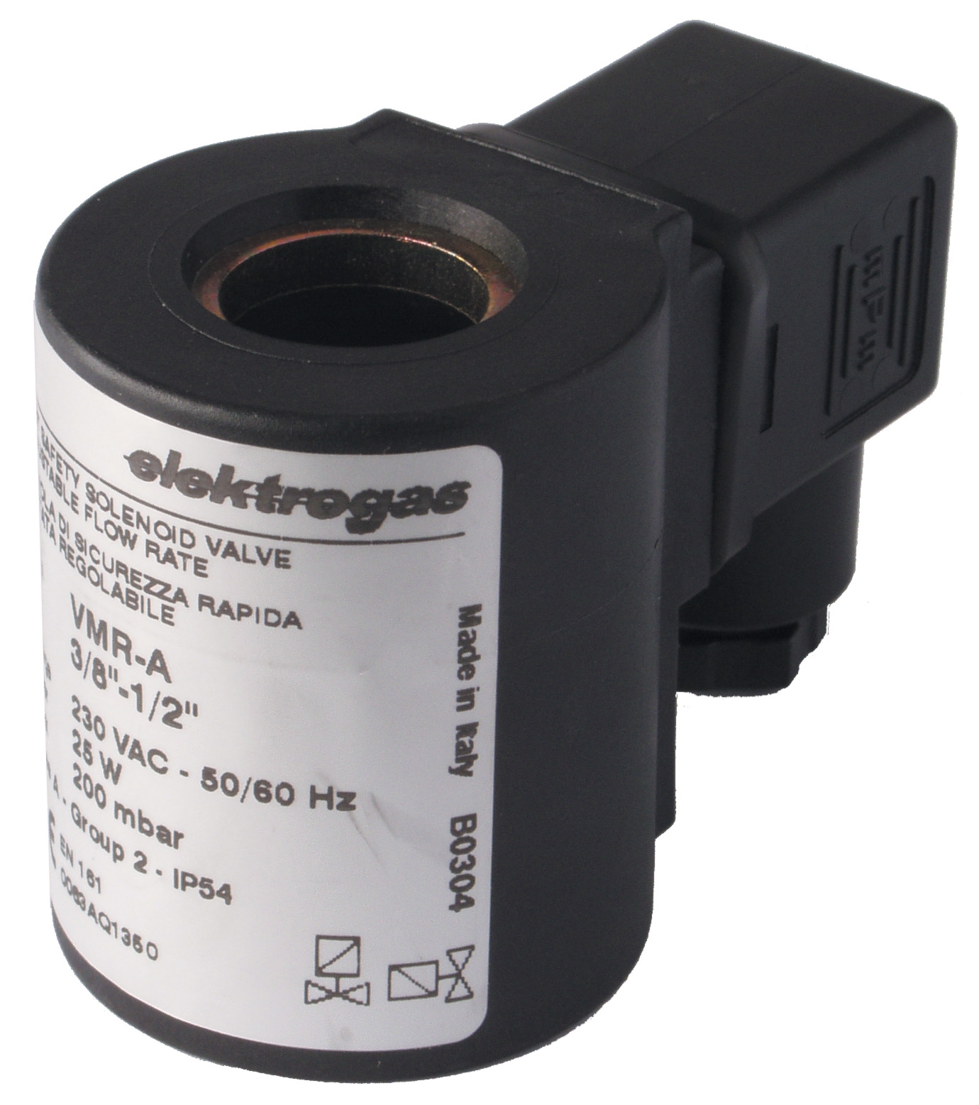
Response time degradation affects burner ignition and modulation speed. Slow valve opening indicates mechanical friction from deposits or failing solenoid coils. The CBM solenoid coil designs (such as the 1930.3100 and 1930.3700 series) employ robust armature designs specifically engineered to maintain crisp response times even in contaminated environments, but coil windings can still degrade from electrical stress or thermal cycling.
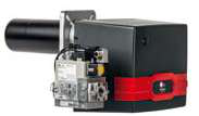
Complete valve blockage represents the most severe failure mode. Particulate accumulation, ice formation from moisture-laden gas, or chemical deposits can completely obstruct flow. FBR burner systems operating at maximum capacity (such as the XP 60 CE TC EVO reaching 630 kW) generate high thermal stress that accelerates deposit formation in downstream regulation components.
Diagnostic Procedures and Technical Testing for Gas Valve Systems
Systematic diagnosis requires both field observation and technical measurement. Begin with visual inspection and progress to quantitative testing using appropriate instrumentation.
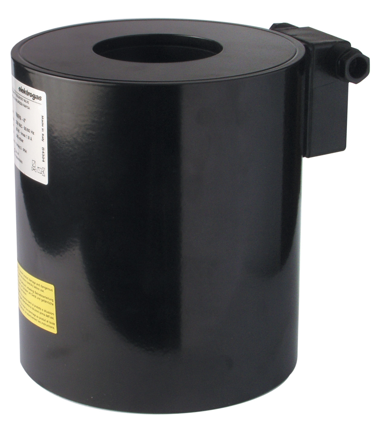
Visual Inspection Phase: Examine external solenoid coils for corrosion, water damage, or mechanical damage. CBM coil assemblies like the ELK26121 (230V VML 2½-3" 200mbar) and ELK26302 (230V EVRMNCOT 3/8"-1" 600mbar-6bar) feature robust enclosures, but connectors and cable entries remain vulnerable to moisture ingress. Check valve body for weeping leaks at seals—minor weeping indicates seal degradation requiring valve replacement. Inspect inlet and outlet ports for visible particulate or discoloration suggesting internal contamination.
Pressure Testing: Using calibrated digital pressure gauges, measure system pressure at valve inlet and outlet. Compare actual readings against design specifications. For example, CBM EVRMNCOT coils operate across 600mbar to 6bar range—verify your system pressure falls within this envelope. Pressure differential across the valve should match design parameters (typically 50-200 mbar for proper modulation). Excessive differential indicates downstream blockage; insufficient differential suggests upstream pressure loss or regulator malfunction. Document pressure readings during burner operation at minimum, modulation mid-point, and maximum load to identify pressure stability issues.
Flow Rate Measurement: Measure actual gas flow rate using a calibrated orifice plate meter or turbine flow meter. Compare against design specifications. For FBR XP 60 CE TC EVO burners, minimum flow should achieve 232 kW and maximum flow should reach 630 kW. If actual flow deviates more than ±5% from specification, internal valve restriction or modulation calibration drift is likely. Progressive flow deviation over weeks suggests gradual contamination.
Solenoid Coil Performance Testing: Measure solenoid coil resistance and voltage draw. A 230V CBM coil should draw approximately 8-12W at rated voltage. If actual draw drops significantly below specification, winding insulation degradation is probable. If draw increases beyond specification, coil short-circuits or armature stiction (friction) is occurring. Test coil response time by energizing the solenoid while observing downstream pressure change—response should be <200 milliseconds. Slow response indicates mechanical friction or weak magnetic force.
Flame Analysis: For burner systems like the FBR XP 80/M reaching 850 kW maximum output, observe flame stability and color. Blue flame indicates complete combustion; yellow/orange flame suggests incomplete mixing caused by valve flow problems. Flame flutter or cycling indicates valve hunting or pressure instability. Use infrared thermography to identify localized overheating suggesting hot spots from improper gas distribution.
Step-by-Step Troubleshooting and Optimization Procedure
Step 1: Establish Baseline Performance Data
Before troubleshooting, document baseline measurements: system pressure (inlet/outlet), flow rate, burner flame appearance, thermal output, solenoid coil voltage and resistance, response times, and ambient conditions. This baseline enables objective comparison and identifies subtle degradation.
Step 2: Verify Gas Supply Quality
Test gas supply pressure stability and composition. Pressure fluctuations ±10% or greater indicate upstream regulator issues unrelated to the control valve. Request gas analysis from your supplier to confirm absence of excessive moisture, particulates, or corrosive compounds. Moisture content exceeding 50 mg/m³ causes condensation in valve bodies.
Step 3: Clean or Replace Strainers and Filters
Remove inlet strainers and inspect for debris. Most industrial gas systems should include 100-micron or finer filtration upstream of solenoid valves. If filters show significant contamination, this is your root cause. Clean or replace filters and restart troubleshooting from Step 2.
Step 4: Test Solenoid Coil Function
De-energize the system. Using a multimeter, measure solenoid coil resistance. Compare against manufacturer specification (typically 500-2000 ohms depending on voltage). Open-circuit resistance indicates failed winding; very low resistance indicates short-circuits. Replace faulty coils—the CBM ELK26121, ELK26302, and ELK26326 coils are field-replaceable components.
Step 5: Perform Pressure and Flow Testing
Re-energize system with all safety interlocks active. Measure and compare inlet/outlet pressures and flow rates against baseline data. Significant pressure drop indicates valve port restriction—internal cleaning or valve replacement is required. Flow deviation suggests modulation calibration drift or mechanical restriction.
Step 6: Optimize Modulation and Pressure Settings
For modulating systems, adjust minimum pressure set point (typically 50-100 mbar above load requirement) to ensure stable modulation across turndown range. Verify maximum pressure relief point is set 10-15% above maximum operating pressure. Document all adjustments.
Best Practices for Sustained Gas Valve Optimization
Preventive Maintenance Schedule: Establish quarterly visual inspections, semi-annual pressure/flow testing, and annual solenoid coil performance verification. In tropical Singapore climates with high humidity, increase inspection frequency to monthly, particularly for systems in marine or chemical environments.
Contamination Prevention: Install high-efficiency gas filters (100-micron minimum) upstream of all solenoid valves. Consider moisture separators for compressed gas applications. For low-pressure systems (200 mbar or lower), add differential pressure gauges to monitor filter loading—replace filters when pressure drop exceeds 100 mbar.
Pressure Stability: Maintain system pressure stability within ±5% using properly calibrated primary and secondary regulators. Pressure cycling indicates regulator hunting or oversized primary regulators. Install solenoid pilot modules to isolate valve operation from upstream pressure fluctuations.
Documentation and Trending: Record all measurements in a maintenance log. Track pressure, flow, coil resistance, and response time trends over months. Deteriorating trends enable predictive replacement before valve failure impacts production.
Component Selection: When replacing solenoid coils, match voltage, pressure rating, and flow capacity exactly. CBM coils are available in multiple voltage options (12V AC/DC, 24V AC, 110V, 230V) and pressure ranges. The ELV93006 24V AC coil provides compatibility across multiple ELV burner valve series, while FBR burner systems require specific matching between burner model and regulation components.
Closing and Next Steps
Gas valve optimization is an ongoing process requiring systematic observation, accurate measurement, and evidence-based adjustment. The troubleshooting methodology outlined here applies across valve types and burner configurations—from compact FBR XP 60 systems to large-scale installations. By implementing these diagnostic procedures and preventive practices, Singapore industrial professionals can achieve sustained burner performance, reduce unplanned downtime, and extend component lifespan significantly.
For complex systems, multiple valve stages, or persistent optimization challenges, 3G Electric's technical team can provide on-site diagnostics and system optimization consultation. We maintain inventory of CBM solenoid coils and FBR burner components and offer technical support tailored to Singapore industrial environments. Contact 3G Electric today to discuss your gas valve performance challenges and receive expert guidance specific to your installation.